Following up the home energy meter post based on an ESP8266 and PZEM-004T hardware, this post describes succinctly the software for using the energy meter.
There are at least two components to the solution:
ESP8266 software for driving the power meter and make the measurements.
The backend software for receiving and processing data.
The ESP8266 software:
The power meter software for the ESP8266 available on this GitHub repository, uses an available PZEM-004T library for accessing the power meter, and sends the collected data through MQTT to any subscribers of the power meter topic.
I’m using the convention that is also used on Thingsboard, namely an MQTT attributes topic to publish the device status, and a telemetry topic to post the data in JSON format.
Around lines 80 on main.cpp of PowerMeter sources, the topics are defined as:
MQTT_ClientID is defined on the secrets.h file, where we also define a list of available WIFI connections for our ESP8266. The attributes topic periodically sends the current device status (RSSI, HEAP, wifi SSID), while the data on the telemetry topic is fed into a timeseries database such as InfluxDB where then a Grafana Dashboard shows and allows to see the captured data across time.
As also my previous post regarding framework and libraries versions, I needed to block the ESP8266 framework version and the SoftwareSerial library because the combination of these with the PZE-004T library was (is ?) broken of more recent versions. As is currently defined on the platformio.ini file, the current set of versions, work fine.
A lot of people had problems working with the use of SoftwareSerial library for the PZEM library to communicate with the hardware. The issue, that I accidentally found out, are related with timing issues to communicate with the PZEM hardware. There are periods of time that the PZEM is not responsive, probably because is making some measurement.
The solution to this issue is at start up to try the connection during some time, at 3 seconds interval until it succeeds. After the connection is successful, we need to keep an interval around one minute between reads to encounter no issues/failures . If this interval is kept, the connection to the PZEM hardware works flawlessly, at least with the hardware that I have.
So the connection phase is checked and tried several times to synchronize the ESP8266 with the PZEM, and them every single minute there is a data read. If the interval is shorter, lets say, 30s, it will fail, until the elapsed time to one minute is completed.
The firmware solves the above issue, and after reading the data, it posts it to a MQTT broker. The firmware also makes available a web page with the current status and measurements:
Power Meter Web Page
Then there are other bits, namely since the meter will be on the electric mains board, an UDP logging facility that allows on the computer to run an UDP server and see what is going on.
The back-end software:
I’ve not done much on this area, since most of it is just standard stuff. An MQTT broker and Node-Red flow. The flow just receives the data, saves it into an InfluxDB database and creates a Node-Red UI dashboard.
Power Meter Node-Red UI
This screenshot shows some of the information that was collected on the last minute and it is updated in real time as soon the PowerMeter information arrives to the MQTT broker.
Future work:
Basically what is missing is two things:
Grafana Dashboard based on the InfluxDB data (Already done, to be described in a future post).
Some kind of exporter to CSV or Spreadsheat to allow further data analysis such as the daily power consumption totals.
Since we will be running a lot of services, each running on its own port, the following configuration, is optional, but allows to access all services through the same entry point by using Nginx server as a reverse proxy to Node-Red, Node-Red UI/Dashboard, Node-Red Worldmap and Grafana.
With this configuration the base URL is always the same without any appended ports, and the only thing that changes are the URL path:
The configuration files will reside in /etc/nginx directory. Under that directory there are two directories: sites-available and sites-enable where the later normally contains a link to configuration files located at sites-available.
At that directory there is a file named default that defines the default web site configuration used by Nginx. This is the file where we will add the reverse proxy directives.
Reverse proxy for Node-Red and Node-Red Contrib Worldmap
For setting up the reverse proxy for Node-Red we must first change the base URL for Node Red from / (root) to something else that we can map the reverse proxy.
For this we will need to edit the settings.js file located on the .node-red directory on the home path of the user running Node-Red.
We need to uncomment and change the entry httpRoot to point to our new base URL.
Note the following: The first location defines the reverse proxy URL /nodered to be served by the backend server http://127.0.0.1:1880. The incoming path, /nodered, will be passed to the backend server URL /nodered, since paths are passed directly. No need to add the /nodered path to the backend server definition.
Also I’m using the 127.0.0.1 address instead of localhost to avoid the IPv6 mapping to the localhost. In this way I’m sure that IPv4 will be used.
The location mapping for /nodered will make all the functionality of node red to work as it should at the base url /nodered. But some nodes, like node-red-contrib-worldmap will request to the proxy server ignoring the node-red base root map. Hence the /socket.io mapping. It will allow the worldmap nodes to work, but will stop this mapping to be used for something else.
Reverse proxy for Grafana
Setting up the reverse proxy for Grafana we can, and should use the following documentation: Grafana Reverse Poxy. For me the following configuration worked:
First edit the [server] section on the Grafana configuration file grafana.ini located at /etc/grafana.
Uncomment and edit the following lines:
[server]
# Protocol (http or https)
protocol = http

# The ip address to bind to, empty will bind to all interfaces
;http_addr =

# The http port  to use
http_port = 3000

# The public facing domain name used to access grafana from a browser
domain = server.domain.com

# Redirect to correct domain if host header does not match domain
# Prevents DNS rebinding attacks
;enforce_domain = false

# The full public facing url you use in browser, used for redirects and emails
# If you use reverse proxy and sub path specify full url (with sub path)
root_url = http://server.domain.com/grafana/
Note the ending slash at the root_url. The same applies to the Nginx configuration
The files for the Nginx configuration are the same as the above configuration for reverse proxy.
We just need to add the following section after the previous location directives:
We should now restart nginx to refresh the configuration, and all should be working as it should by accessing the Grafana dashboard at http://server.domain.com/grafana
On the previous post we’ve installed and the base software for our Grafana based dash board.
We need now to configure our InfluxDB database and Node Red to start collecting data.
Configuring InfluxDB:
Detailed instructions for configuring an InfluxDB database are on this InfluxDB documentation link..
The main concepts that we need to be aware when using the InfluxDB is that record of data has a time stamp, a set of tags and a measured value. This allows, for example to create a value named Temperature and tag it depending on the source sensor:
This allows to process all the data or only process data based on a certain tag or tags. Values and tags can be created on the fly without previously define them, which is a bit different from standard RDBMS engines.
Creating an InfluxDB database:
To create the database, we need to access the machine hosting the InfluxDB server and execute the command influx:
odroid@odroid:~$ influx
Connected to http://localhost:8086 version 1.2.0
InfluxDB shell version: 1.2.0
> create database SensorData
> show databases
name: databases
name
----
_internal
SensorData

>
Now we have our database created and I’ve named SensorData. To make an example with the above temperature data we can do the following:
> insert Temperature,Sensor=kitchen value=22.1
ERR: {"error":"database is required"}

Note: error may be due to not setting a database or retention policy.
Please set a database with the command "use " or
INSERT INTO .
> use SensorData
Using database SensorData
>
As we can see we need first to select the database where we are going to insert data with the command use SensorData:
> use SensorData
Using database SensorData
> insert Temperature, Sensor=kitchen value=22.1
ERR: {"error":"unable to parse 'Temperature, Sensor=kitchen value=22.1': missing tag key"}

> insert Temperature,Sensor=kitchen value=22.1
> insert Temperature,Sensor=Room1 value=21.9
> select * from Temperature
name: Temperature
time                Sensor  value
----                ------  -----
1487939008959909164 kitchen 22.1
1487939056354678353 Room1   21.9
Note that we can’t use spaces between the Measure name and the tags. The correct syntax is as follows:
Also note that no DDL (data definition language) was used to create the tags or the measured value, we’ve just inserted data for our measurement with the our tags and value(s) without the need of previously define the schema.
Configuring Node-Red
Since we now have a database we can configure the InfluxDB Node Red nodes to store data onto the database:
There are two types of InfluxDB nodes, one that has an Input and Output and other that only has Input. The former is for making queries to the database where we provide on the input node the query, and on the output the results are returned. The later is for storing data only onto the database.
For both nodes we need to configure an InfluxDB server:
We need to press the Pen icon right next to the server to add or reconfigure a new InfluxDB server:
A set of credentials are required, but since I’ve yet configured security, we can just put admin/admin as username and password. In a real deployment we must activate security.
From now on it is rather simple. Referring to InfluxDB node configuration screenshot (Not the InfluxDB server configuration) we have a configuration field named Measurement. This is our measure name that we associate a value. Picking up on the above example with the Insert command it will be Temperature, for example.
Now if the msg.payload provided has input to the node is a single value, let’s say 21, this is equivalent to do:
Insert Temperature value=12
We other formats for msg.payload that allows to associate tags and measures. Just check the Info tab for the node.
Simple example:
The following flow shows a simple example of a value received through MQTT, in this case the free heap from one of my ESP8266 and its storage in InfluxDB:
Just a quick hack to use the Node Red dashboard to monitor some of the UPS values that is attached to My Synology NAS.
Gathering the data and feeding it to Node-Red
First I thought to do some sort of Python or NodeJS program to run the upsc command, process the output and feed it, through MQTT, to Node Red.
But since it seemed to me a bit of overkill to just process a text output, transform it to JSON and push it through MQTT by using a program, I decided that I’ll use some shell scripting, bash to be more explicit.
I’m running on my Odroid C1+ “server” all the necessary components, namely Node Red with the Dashboard UI module.
So on Odroid I also have the ups monitoring tools, and upsc outputs a text with the ups status:
So all we need now is to transform the above output from that text format to JSON and feed it to MQTT.
This means that we need to put between ” the parameter names and values, replace the : by , and also we need to replace the . on parameter names to _ so that in Node Red javascript we don’t have problems working with the parameter names.
Since I’m processing each line of the output, I’m using gawk/awk that allows some text processing. The awk program is as follow:
BEGIN {print "{"}
 {
   print lline  "\42" $1 "\42:\42"$2"\42"
 }
 {lline =", "}
END {print "}"}
This will at the beginning print the opening JSON bracket, then line by line the parameter name and value between ” and separated by : .
The lline variable at the first line is empty, so it prints nothing, but at the following lines it prints , which separates the JSON values.
We just need awk now to recognize parameters and values, and that is easy since they are separated by :
So if the above code is saved as procupsc.awk file, then the following command:
Now all we need is to feed the output to the MQTT broker, and for this I’ll use the mosquitto_pub command, that has a switch that accepts the message from the standard input:
So we define the host and the topic: upsmon and the message is the output of the previous command (the -s switch).
All we need now is on Node Red to subscribe to the upsmon topic and process the received JSON object.
Since I’m running this periodically on crontab, I also add the PATH variable so that all files and commands are found.
The complete script is as follows:
# m h  dom mon dow   command
*/5 * * * * /home/odroid/upsmon/upsmon.sh
Node Red processing and visualization
On node red side, now is easy. We receive the above upsc JSON object as a string on msg.payload, and we use the JSON node to separate into different msg.# variables.
From here we just feed the data to charts and gauges. The code is:
I run many services on my Odroid C1+ including Node-Red. But since NodeJs on Odroid C1+ is version v0.10 is starting to be seriously old for running Node-Red or other NodeJS dependent software.
So my quick instructions for upgrading NodeJS and Node-Red on the Odroid C1+
Upgrading NodeJS
First verify what version is available/installed on the Odroid:
Since I’ve already had previously installed a more recent version of NodeJS (the node command), the version used by Node-Red is v0.12.14 while the default NodeJS version is v0.10.25.
We can also, and should, check the npm version:
odroid@odroid:~$ npm -v
2.15.1
We also need to find what architecture we are using, just for completeness since ODroid C1+ is an ARM7 based architecture:
odroid@odroid:~$ uname -a
Linux odroid 3.10.96-151 #1 SMP PREEMPT Wed Jun 15 18:47:37 BRT 2016 armv7l armv7l armv7l GNU/Linux
This will allow us to download the correct version of the NodeJS binaries from the NodeJS site: NodeJS downloads.
In our case we choose the ARM7 architecture binaries, which at the current time is file: node-v6.9.2-linux-armv7l.tar.xz
So I’ve just copied the link from the NodeJS site and did a wget on the Odroid:
I then created a working directory and “untared” the file:
odroid@odroid:~$ mkdir nodework
odroid@odroid:~$ cd nodework
odroid@odroid:~/nodework$ tar xvf ../node-v6.9.2-linux-armv7l.tar.xz
odroid@odroid:~/nodework$ cd node-v6.9.2-linux-armv7l/
odroid@odroid:~/nodework/node-v6.9.2-linux-armv7l$
Since there isn’t an install script we need to move the new NodeJS files to the correct locations:
Binaries to /usr/bin
Include files to /usr/include
Libs files to /usr/lib
Copy the binaries, replacing, if existing the older versions:
From the Node-Red startup log, we can see the previous versions of node-red and nodejs used:
Welcome to Node-RED
===================

28 Dec 17:55:40 - [info] Node-RED version: v0.15.2
28 Dec 17:55:40 - [info] Node.js  version: v0.12.14
28 Dec 17:55:40 - [info] Linux 3.10.96-151 arm LE
28 Dec 17:55:42 - [info] Loading palette nodes
28 Dec 17:55:50 - [info] Dashboard version 2.1.0 started at /ui
28 Dec 17:55:54 - [warn] ------------------------------------------------------
28 Dec 17:55:54 - [warn] [rpi-gpio] Info : Ignoring Raspberry Pi specific node
28 Dec 17:55:54 - [warn] ------------------------------------------------------
Starting up Node-Red should show now the new software versions:
Welcome to Node-RED
===================

1 Jan 20:35:46 - [info] Node-RED version: v0.15.2
1 Jan 20:35:46 - [info] Node.js  version: v6.9.2
1 Jan 20:35:46 - [info] Linux 3.10.96-151 arm LE
1 Jan 20:35:47 - [info] Loading palette nodes
1 Jan 20:35:54 - [info] Dashboard version 2.2.1 started at /ui
As we can see in my previous post, for securely store data from a device, we should make the data secure during transport and tamper proof. This can be achieved by using encryption, but the use of encryption only does not solve some attacks, like replay attacks.
So a scheme where data is encrypted and associated with a sequence number is used, to have transport security and replay attack protection, and on the previous post we’ve implemented the base framework that allows the support of our requirements.
So the device generates, for example, the following message:
{ "data":{"value": 300} , "SEQN": 120 }
meaning that it wants to send to the backend the JSON Object {“value”: 300}, and the current Sequence number is 120. On the next message the sequence number should be 121, but that is supposing that algorithm for the sequence number is to increase it one by one per message.
Giving the message, we encrypt it now with our device key, and build another JSON object, the one that will be sent to the Node-red based backend:
{ "msg":"U2FsdGVkX1..."}
Since we still don’t have our device ready to send messages, we will build a simple NodeJs program to generate the messages:
mkdir ~/gen
cd ~/gen
npm init   (Just accept the defaults)
npm install crypto-js --save
npm install request --save
And the code to generate our message is as follow:
var CryptoJS = require("crypto-js");
var request = require('request');

// API endpoint.
var apiEP = 'http://localhost:1880/data/';
var deviceID = '12FA';

// The AES encryption/decription key to be used.
var AESKey = '2B7E151628AED2A6ABF7158809CF4F3C';

// The JSON object that we want to encrypt and transmit
var msgObjs = {"data":{"value":300}, "SEQN":121 };

// Convert the JSON object to string
var message = JSON.stringify(msgObjs);
console.log("Message: " , message );

// Encode the string to base64. Not really needed.
message = new Buffer(message).toString("base64");
console.log("Message B64: " , message );

// Encrypt
var ciphertext = CryptoJS.AES.encrypt(message, AESKey );

console.log("Cypher text: " ,  ciphertext.toString(CryptoJS.enc.base64) );
console.log(" ");
console.log("Let's call the Node-Red API end point: ");

var URL = apiEP + deviceID;
var rawdata = ciphertext.toString(CryptoJS.enc.base64);

console.log(" Calling end point: " , URL);
console.log(" RawData: " , rawdata );

// Let's call the REST API end point.
request( {
    url: URL,
    method: "POST",
    json: true,
    body: { "msg": rawdata}
    } ,
    function (error, response, body) {
        if (!error && response.statusCode == 200) {
            console.log(" ");
            console.log("REST API Output: ");
            console.log(body)
        }
    }
);
console.log("=============================================================================");
console.log(" ");
console.log("Let's do a sanity check: Let's decrypt: ");

// Decrypt
var bytes  = CryptoJS.AES.decrypt(ciphertext.toString(), AESKey );
var plaintext = bytes.toString(CryptoJS.enc.Utf8);

console.log("Decrypted message UTF8 decoded: ", plaintext);
console.log(" ");

console.log("Decrypted message: " , new Buffer(plaintext , 'base64').toString('ascii'));
We can modify the message by modifying the msgObjs variable. We run this program by executing node index.js and at the end the Node-Red answer should be displayed under REST API Output.
If everything is setup correctly the REST API should return:
REST API Output:
{ status: 'OK' }
But calling a second time without modifying the sequence number should fail:
REST API Output:
{ status: 'NOT OK' }
The Node-Red flow:
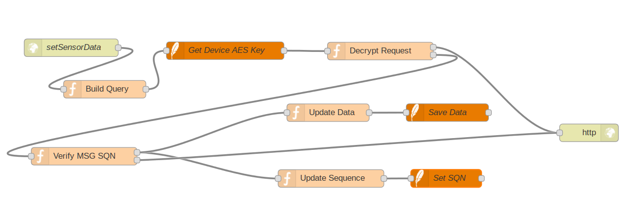
The Node-Red flow, receives the REST POST request for the device ID, obtains from the database the private key associated to the device, decrypts the payload, and checks the message sequence number vs the database sequence number. By design it allows the device to send messages above the current sequence number to allow message gaps (messages that where lost). We can, if needed, process this gaps so we can have an idea of how many messages that we are loosing.
If the decryption is successful and the sequence number is ok, we increment the sequence number to the next value, and store the data:
Node-Red Data Storage flow
The code is as follow:
[{"id":"501864bd.eea2ec","type":"sqlitedb","z":"ee002ffe.ffd9e8","db":"/home/odroid/Databases/wsn.db"},{"id":"9e2ef.10b2b512","type":"http in","z":"ee002ffe.ffd9e8","name":"setSensorData","url":"/data/:id","method":"post","swaggerDoc":"","x":142.1666717529297,"y":812.0833587646484,"wires":[["fa205b8f.8de96"]]},{"id":"fa205b8f.8de96","type":"function","z":"ee002ffe.ffd9e8","name":"Build Query","func":"// Get the device id\nvar deviceId = msg.req.params.id;\n\n// Build the query. The SQLITE node requires the query in msg.topic\nmsg.topic=\"Select * from Devices where deviceID='\" + deviceId +\"'\";\n\n// Let's pass these parameters forward on its on variables:\nmsg.deviceid = deviceId;\nmsg.rawdata = msg.payload;\n\nreturn msg;","outputs":1,"noerr":0,"x":199.1666717529297,"y":882.7499694824219,"wires":[["94004285.aa1418"]]},{"id":"94004285.aa1418","type":"sqlite","z":"ee002ffe.ffd9e8","mydb":"501864bd.eea2ec","name":"Get Device AES Key","x":404.16668701171875,"y":817.0833435058594,"wires":[["7dd8f03c.ab2778"]]},{"id":"d0ed1bda.b15428","type":"http response","z":"ee002ffe.ffd9e8","name":"","x":1023.1666870117188,"y":956.8333435058594,"wires":[]},{"id":"7dd8f03c.ab2778","type":"function","z":"ee002ffe.ffd9e8","name":"Decrypt Request","func":"var cryptojs = context.global.cryptojs;\ntry {\n // Get the key, Sequence number and the raw encrypted data\n var AESKey = msg.payload[0].deviceKey;\n msg.dbSQN = msg.payload[0].deviceSQN; // Obtain also the currrent SQN on the database\n \n var rawdata= msg.rawdata.msg;\n \n node.log( msg.devSQN );\n // Decrypt the payload data with the device key. \n // It returns a string sequence of bytes.\n var bytes = cryptojs.AES.decrypt( rawdata, AESKey );\n \n // Convert bytes to an UTF8 plain string\n var plaintext = bytes.toString(cryptojs.enc.Utf8);\n node.log( plaintext );\n // Convert from base64 to string\n msg.payload = new Buffer(plaintext , 'base64').toString('ascii');\n\n return [ null , msg ]; // Exit the function at output 2.\n \n} catch (err) {\n msg.payload = { \"status\":\"NOT OK\"};\n msg.statusCode = 500; // Set internal server error\n node.log(\"Invalid deviceID request for GET SQN Operation\");\n return [ msg , null ]; // Exit the function at output 1\n}\nreturn msg;","outputs":"2","noerr":0,"x":668.1666870117188,"y":817.7499694824219,"wires":[["d0ed1bda.b15428"],["c7be8b09.893b9"]]},{"id":"c7be8b09.893b9","type":"function","z":"ee002ffe.ffd9e8","name":"Verify MSG SQN","func":"// At this point we should have:\n// msg.payload with the sequence number in JSON: { SEQN: 200} and the rest of the message\n// msg.deviceid with the device id\ntry {\n var msgObj = JSON.parse(msg.payload);\n var msgSeqn = msgObj.SEQN; // The sequence number that the device as sent\n var msgData = msgObj.data; // The data sent\n \n if ( msg.dbSQN <= msgSeqn ) { // Valid Sequence number\n node.log( \"Sequence is VALID!!!!!\");\n msg.payload = { \"status\":\"OK\"};\n msg.data = msgData;\n msg.devSQN= msgSeqn;\n return [ msg, msg];\n } else {\n node.log( \"Sequence is invalid!!!!\");\n msg.payload = { \"status\":\"NOT OK\"};\n return [ null , msg ];\n }\n} catch( e ) {\n node.log(\"Error verifying SEQN...\") \n msg.payload = { \"status\":\"Internal Error\"};\n return [ null , msg ];\n}","outputs":"2","noerr":0,"x":164.1666717529297,"y":996.7499694824219,"wires":[["c8ce0d1c.589058","533d8275.e04474"],["d0ed1bda.b15428"]]},{"id":"c8ce0d1c.589058","type":"function","z":"ee002ffe.ffd9e8","name":"Update Sequence ","func":"\n var dbSQN = msg.devSQN + 1; // It allows message gaps.\n\n msg.topic=\"Update Devices Set deviceSQN= \" + dbSQN + \" Where deviceID='\" + msg.deviceid +\"'\";\n \n //node.log(\"SQL: \" + msg.topic );\nreturn msg;","outputs":1,"noerr":0,"x":584.1666870117188,"y":1034.5833740234375,"wires":[["bef21dc4.4642a"]]},{"id":"bef21dc4.4642a","type":"sqlite","z":"ee002ffe.ffd9e8","mydb":"501864bd.eea2ec","name":"Set SQN","x":780.1666870117188,"y":1034.4166259765625,"wires":[[]]},{"id":"533d8275.e04474","type":"function","z":"ee002ffe.ffd9e8","name":"Update Data","func":" // Let's extract the data.\n // This step should be modified as needed.\n var data = msg.data.value;\n msg.topic=\"Insert into Data Values ( '\" + msg.deviceid + \"', CURRENT_TIMESTAMP , \" + data + \")\";\n \n //node.log (\"Data: \" + data );\nreturn msg;","outputs":1,"noerr":0,"x":579.1666870117188,"y":922.5833435058594,"wires":[["770abb44.6f54d4"]]},{"id":"770abb44.6f54d4","type":"sqlite","z":"ee002ffe.ffd9e8","mydb":"501864bd.eea2ec","name":"Save Data","x":782.1666870117188,"y":922.4165954589844,"wires":[[]]}]
And so the only thing missing is the ESP8266 code to call and setting data using the encrypted transport. For implementing that we will be using the Sming framework that will use and call the above defined API on this post and previous.
One off my posts is how to log data that is sent from an ESP8266 device into a MySql database: Logging data on a MySQL database by using the Nodemcu firmware and some PHP on the server side. Keep in mind that post/solution is/was just a quick hack to move data from the ESP8266 into a database. There are better solutions for implementing a process that receives data and stores data from the ESP8266, or any other device, into a database.
Why we should improve the “hack”? Well there is no security or authentication on that example. If deployed in a real world scenario, someone could just inject random value data into MySQL or do some other nasty things, like SQL Injection.
So the idea of this post is to do something more generic and more robust than the original post, namely build a server backend that can satisfy these following points:
Authentication – Only allow authorized devices to log data into a database
E2EE: End to End Encryption – Secure data while in transit from the device to the final storage
MySQL database is hardcoded: – The original example is hardcoded to MySQL. Let’s do something more generic, namely something that can store data on other databases.
One natural candidate for building this generic backend is IBM Node Red. Node Red would allows us to keep developments to a minimum and still have great flexibility.
Options to connect to the backend:
There are several options to get data from the devices into a backend database server securely. Let’s see some of them:
Implement a native database driver on the device:
Ok, this crosses the mind of several people as a possible solution. But we are talking on implementing a database driver on devices that have constrained resources (memory, CPU, connectivity!). It also means that the database must be exposed directly on the network so that the devices can access it directly. Also, in most of the database drivers, the database connection needs to have a constant network connection. So this solution might make sense if the device is an RPi or some other larger/powerful device with a permanent network connection, but it’s not a good idea for a device like an ESP8266 (Not to mention that it might be just plain impossible to port the database driver).
HTTP based interface: REST, SOAP, plain HTTP:
This is far easier to implement since it uses plain HTTP (as the my original example from the ESP8266 to MySQL example), needs no permanent connection to the server, and we can implement authentication and E2EE either by configuring the backend server to use HTTPS or by encrypting data by ourselves. Still HTTPS could be difficult to use, but HTTP is almost universal. So HTTP(S) call to a REST/SOAP server is a good candidate.
MQTT data publishing:
MQTT is also a good candidate but it won’t work well for devices that have intermittent connectivity since MQTT needs a permanent TCP/IP connection to be available from the device to the MQTT broker. MQTT recognizes this limitation, and there is MQTT-SN, for sensor networks, that doesn’t demand a TCP/IP connection.
Authentication and E2EE can be implemented at the protocol level, namely by using authentication on the broker and accessing the broker with TLS/SSL. Also MQTT is not the only alternative, COAP and AMQP are also valid solutions.
So using a native database driver on the device is out of question and so far it seems that the HTTP, MQTT(-SN) and/or COAP protocols are the best way to transfer data from the devices to the backend. Still even implementing these protocols on the end devices might not be good enough for very constrained devices, but that is another issue…
Anyway HTTP and MQTT support, is as of today, pretty standard on all the available firmwares for the ESP8266. But using HTTPS and MQTT over SSL support might still not possible to use1.
So on this post I’ll just use plain REST over HTTP with the payload encrypted with AES.
This means that before we send our data, we will encrypt it with a key (our device key) and send it to the server. The server also holds our device key, and decrypts the data.
The basics:
Since we want to encrypt data during transmission and then decoding at the other, we need to setup a secure channel between our source and our destination database. For the sake of an example I’ll just AES encrypt the source data and decrypt it at the destination. Encryption will solve the possibility of someone eavesdropping the data but it won’t protect from replay attacks, which means someone can grab the full encrypted data and try to flood our server with N repetitions of the same data.
To solve this latest issue, we will add a sequence number to each request before is encrypted and at the receive side we check if the sequence number is not repeated. The sequence number will also allow us to see if we have lost any messages.
So we will use just a plain private shared key, without any kind of key management, or any kind of Public key based solution, to setup our encrypted channel.
Setting up Node-Red:
For setting up Node-red we need to do the following:
– Install the Sqlite node for accessing Sqlite databases:
Restart Node-Red so the new Sqlite nodes appear at the nodes pallet.
Implementing the backend server side:
Our backend server based on Node-red should now allow to do the following:
– Decrypt the receiving data sent by the devices.
– Check if the sequence number for the sending device is valid. If not reject the request.
– Store the received data on the database.
The requesting device at startup, since it might not have any kind of permanent storage, might not know what is/was the current/correct sequence number. There are at least three solutions for this:
Case 1: The device requests what is the current sequence number for itself at startup.
Case 2: The device starts at zero, again, but informs the backend that it has reset the sequence to zero
Case 3: The device starts at a random number and informs the backend what is now the current sequence number.
As we can see Case 2 is just a special case of Case 3. We just need to make sure that:
On the first case the backend response with the current sequence number is in fact from a trusted backend
On the other cases the backend must validate that the device is who claims to be and sets the new sequence number.
Also, as for the orinial problem of setting data with protection from replay attacks, Case 2 and Case 3, suffer from the same issue. We also should also protect this calls from replay attacks, but for the sake of simplicity, we not going to do that on this cases.
For implementing the solution we need two tables: One for the device id-> device key association and current sequence number, and the table for storing data. In this last case let’s just suppose it is a simple value.
TABLE Devices
      deviceId: String,
      deviceKey: String,
      deviceSQN: integer

TABLE Data
      deviceId: String,
      dataDate: date
      dataValue: integer
We can create both tables on MySQL/PostGres/SQLITE, or for a real example, create the Devices table on a relational standard RDBMS as MySQL/SQLITE, and the Data “table” available on a timeseries database like InfluxDB.
We going to keep everything, for now on SQLITE, since we going to use the Node-Red Sqlite node:
Creating the database:
On the machine running Node-Red, create the database and tables:
cd ~
mkdir Databases
cd Databases
We create now the database and tables:
pcortex@pcortex:~/Databases$ sqlite3 wsn.db
SQLite version 3.8.2
Enter ".help" for instructions
Enter SQL statements terminated with a ";"
sqlite> .databases
seq  name             file
---  ---------------  ----------------------------------------------------------
0    main             /home/pcortex/Databases/wsn.db
And now we create the tables:
sqlite> create table if not exists Devices ( deviceID String, deviceKey String, deviceSQN INTEGER);
sqlite> create table if not exists Data ( deviceID String, dataDate Date, dataValue Integer);
sqlite> .tables
Data     Devices
sqlite>
We can now just insert some dummy data into the device table:
sqlite> insert into Devices values( '12FA', '2B7E151628AED2A6ABF7158809CF4F3C', 0);
sqlite> select * from Devices;
12FA|2B7E151628AED2A6ABF7158809CF4F3C|0
sqlite>
The process of filling up this tableis another story in itself, so for the purpose of this post we just insert the device id, in this case 12FA, an AES key and the sequence number 0.
Retrieving the Sequence Number (Case 1):
Our device will retrieve the current sequence number using a REST Api GET operation by calling our backend, running on Node-Red. The request for retrieving the sequence number will return an encrypted JSON object as follow:
{"SEQN": 20 }
Where in this case, 20 is the current sequence number stored in the database.
The REST API is built as follow:
Node RED REST API
The HTTP input node will listen to the URL /wsn/:id where id is the device ID for the device that we want to obtain the sequence number. We then, based on the device ID, query the SQLITE Devices table, obtain the current sequence number, encrypt it with the device key and send the response to the requesting device. The requesting party using the device key, decrypts the answer and obtains the sequence number.
[{"id":"501864bd.eea2ec","type":"sqlitedb","z":"ee002ffe.ffd9e8","db":"/home/odroid/Databases/wsn.db"},{"id":"27489da4.ff5382","type":"http in","z":"ee002ffe.ffd9e8","name":"getSensorSEQN","url":"/wsn/:id","method":"get","swaggerDoc":"","x":169.1666717529297,"y":96.0833511352539,"wires":[["e9c38500.a29dc"]]},{"id":"313d3819.34686","type":"http response","z":"ee002ffe.ffd9e8","name":"","x":801.1666870117188,"y":92.00000762939453,"wires":[]},{"id":"aec88434.e67e98","type":"sqlite","z":"ee002ffe.ffd9e8","mydb":"501864bd.eea2ec","name":"Get Device SEQN","x":384.16668701171875,"y":232.75,"wires":[["108630b.69050cf","33e20204.5cbc66"]]},{"id":"108630b.69050cf","type":"function","z":"ee002ffe.ffd9e8","name":"Encrypt response","func":"// Import the global Crypto-js module defined on Node-Red settings.js file\nvar cryptojs = context.global.cryptojs;\ntry {\n // Get the key and the sequence number.\n var AESKey = msg.payload[0].deviceKey;\n var SEQNum = msg.payload[0].deviceSQN;\n\n // Build the new payload. Just the sequence number\n msg.payload = '{\"SEQN\":' + SEQNum + '}';\n\n // Move data to base64\n var bdata = new Buffer(msg.payload).toString('base64');\n\n // Encrypt the data with the device key.\n var ciphertext = cryptojs.AES.encrypt(bdata, AESKey );\n\n // The payload is now the encrypted data\n msg.payload = ciphertext.toString();\n} catch (err) {\n msg.payload = \"\";\n node.log(\"Invalid deviceID request for GET SQN Operation\");\n}\nreturn msg;\n","outputs":1,"noerr":0,"x":650.1666870117188,"y":233.58334350585938,"wires":[["313d3819.34686","33e20204.5cbc66"]]},{"id":"e9c38500.a29dc","type":"function","z":"ee002ffe.ffd9e8","name":"Build Query","func":"var deviceId = msg.req.params.id;\nmsg.topic=\"Select * from Devices where deviceID='\" + deviceId +\"'\";\nreturn msg;","outputs":1,"noerr":0,"x":182.1666717529297,"y":232.58334350585938,"wires":[["aec88434.e67e98"]]},{"id":"9d945f85.62b8a","type":"catch","z":"ee002ffe.ffd9e8","name":"","scope":null,"x":471.16668701171875,"y":93.0833511352539,"wires":[["313d3819.34686"]]},{"id":"33e20204.5cbc66","type":"debug","z":"ee002ffe.ffd9e8","name":"","active":false,"console":"false","complete":"payload","x":635.1666870117188,"y":323.66668701171875,"wires":[]},{"id":"9a0c49f6.f84f","type":"comment","z":"ee002ffe.ffd9e8","name":"REST API - GET operation","info":"Obtains the current Sequence Number for the device","x":144.1666717529297,"y":36.91667175292969,"wires":[]}]
Just copy the above Node-Red flow and use the Import function on Node-Red to paste the code.
We can test the API through wget or curl:
 wget -qO- http://localhost:1880/wsn/12FA
or
 curl -X GET  http://localhost:1880/wsn/12FA
Outputs:
 U2FsdGVkX1+VRlCORJjs2mxxTljfcdu6Z7G8JVyFx7b+jaqKMLeBx4ecLQnjUOYp
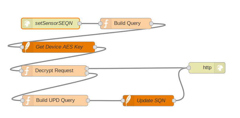
Setting the Sequence Number (Case 2 and 3):
For this case the device defines what sequence number it should use, zero or other random number, encrypts with device key the JSON object { SEQN: # } where # is the sequence number, and wraps it on a JSON POST request to our backend:
For example:
As we’ve referred earlier we wont protect this call from replay attacks, so calling the API with same message over and over will just reset the sequence.
The flow to process the request for reseting the sequence is as follow:
and the code is:
[{"id":"501864bd.eea2ec","type":"sqlitedb","z":"ee002ffe.ffd9e8","db":"/home/odroid/Databases/wsn.db"},{"id":"60f28b66.30c0b4","type":"http in","z":"ee002ffe.ffd9e8","name":"setSensorSEQN","url":"/wsn/:id","method":"post","swaggerDoc":"","x":166.1666717529297,"y":467.0833740234375,"wires":[["78ba9614.8925f"]]},{"id":"78ba9614.8925f","type":"function","z":"ee002ffe.ffd9e8","name":"Build Query","func":"// Get the device id\nvar deviceId = msg.req.params.id;\n\n// Build the query. The SQLITE node requires the query in msg.topic\nmsg.topic=\"Select * from Devices where deviceID='\" + deviceId +\"'\";\n\n// Let's pass these parameters forward on its on variables:\nmsg.deviceid = deviceId;\nmsg.rawdata = msg.payload;\n\nreturn msg;\n","outputs":1,"noerr":0,"x":373.16668701171875,"y":467.2499694824219,"wires":[["76185c6b.95edbc"]]},{"id":"76185c6b.95edbc","type":"sqlite","z":"ee002ffe.ffd9e8","mydb":"501864bd.eea2ec","name":"Get Device AES Key","x":188.1666717529297,"y":532.0833740234375,"wires":[["7fd8ec4.4d1e114"]]},{"id":"7fd8ec4.4d1e114","type":"function","z":"ee002ffe.ffd9e8","name":"Decrypt Request","func":"var cryptojs = context.global.cryptojs;\ntry {\n // Get the key and the raw encrypted data\n var AESKey = msg.payload[0].deviceKey;\n var rawdata= msg.rawdata.msg;\n\n // Decrypt the payload data with the device key. \n // It returns a string sequence of bytes.\n var bytes = cryptojs.AES.decrypt( rawdata, AESKey );\n \n // Convert bytes to an UTF8 plain string\n var plaintext = bytes.toString(cryptojs.enc.Utf8);\n \n // Convert from base64 to string\n msg.payload = new Buffer(plaintext , 'base64').toString('ascii');\n\n return [ null , msg ]; // Exit the function at output 2.\n \n} catch (err) {\n msg.payload = \"\";\n msg.statusCode=500; // Set internal server error\n node.log(\"Invalid deviceID request for GET SQN Operation\");\n return [ msg , null ]; // Exit the function at output 1\n}\nreturn msg;","outputs":"2","noerr":0,"x":176.1666717529297,"y":597.25,"wires":[["4c3674c1.cdde1c"],["8eba7bdc.d8358"]]},{"id":"4c3674c1.cdde1c","type":"http response","z":"ee002ffe.ffd9e8","name":"","x":596.1666870117188,"y":588.8334045410156,"wires":[]},{"id":"6a9430f9.542d08","type":"sqlite","z":"ee002ffe.ffd9e8","mydb":"501864bd.eea2ec","name":"Update SQN","x":435.16668701171875,"y":679.0833740234375,"wires":[["4c3674c1.cdde1c"]]},{"id":"8eba7bdc.d8358","type":"function","z":"ee002ffe.ffd9e8","name":"Build UPD Query","func":"// At this point we should have:\n// msg.payload with the sequence number in JSON: { SEQN: 200}\n// msg.deviceid with the device id\nvar seqnObj = JSON.parse(msg.payload);\nvar seqn = seqnObj.SEQN;\n\nnode.log(\"Seq load: \" + seqn);\n\nmsg.topic = \"update Devices set deviceSQN = \" + seqn +\" where deviceId = '\" + msg.deviceid + \"'\";\n\nreturn msg;","outputs":1,"noerr":0,"x":179.1666717529297,"y":678.75,"wires":[["6a9430f9.542d08"]]}]
For testing we can use sqlite to reset the sequence:
sqlite3 wsn.db
SQLite version 3.8.2 2013-12-06 14:53:30
Enter ".help" for instructions
Enter SQL statements terminated with a ";"
sqlite> update Devices set deviceSQN=30;
sqlite> select * from Devices;
12FA|2B7E151628AED2A6ABF7158809CF4F3C|30
and do the encrypted request:
curl -H "Content-Type: application/json" -X POST -d '{"msg":"U2FsdGVkX1+VRlCORJjs2mxxTljfcdu6Z7G8JVyFx7b+jaqKMLeBx4ecLQnjUOYp"}' http://localhost:1880/wsn/12FA
and see the result:
sqlite> select * from Devices;
12FA|2B7E151628AED2A6ABF7158809CF4F3C|120
We can repeat the request over and over again, and it will be accepted every time since we have no mechanism to stop that.
Conclusion:
We can see that the most secure way to use the Sequence Number is to only use Case 1, requesting it, and not Case 2 and Case 3 where the devices set’s the sequence and is vulnerable to replay attacks.
So this is already a long post and there are still several things to do:
– The data storage request handler so we can finally transmit securely our data.
– The device code on the ESP8266 to execute the requests.
Just a quick install instructions to use the Crypto-Js library on Node-Red, so that we can use encryption/decryption functions and hash functions like AES and SHA256 on workflows.
Installation and configuration:
First move to the Node-Red install directory. The right directory can vary from platform to platform.
In my case I’m running Node-Red on my Odroid C1+ controlled by the PM2 process manager:
cd .node-red
npm install crypto-js
Edit the settings.js file to add the global defined library:
I already have the node-gcm module to use it for Android notifications from Node-Red workflows.
Restart Node-Red. In my case as: pm2 restart node-red
How to use:
We can now use the Crypto-js functions on our workflow functions like this:
// Import the global Crypto-js module defined on Node-Red settings.js file
var cryptojs = context.global.cryptojs;

// Move data to base64
var bdata = new Buffer(msg.payload).toString('base64');

// Encrypt the data with the device key.
var ciphertext = cryptojs.AES.encrypt(bdata, "2B7E151628AED2A6ABF7158809CF4F3C" );

// The payload is now the encrypted data
msg.payload = ciphertext.toString();

return msg;
That’s it. We can now access the provided functions by the Crypto-js library from our Node-Red workflows.
On the ARM based small computers front, running Linux or Android, there are several contenders, being the most famous one the Raspberry PI. Due to the huge community and documentation available the Raspberry Pi is the most chosen for a whole range of projects including low power servers, controllers, media players and so on.
Anyway, there are several alternatives, even cheaper, than the RPi. For example the 15$ Orange Pi looks promising on the price front, but not on the software side due to the Allwinner chip, it doesn’t look very promising without closed binary blobs. Other alternatives are the Banana Pi, Beaglebone board, Cubie board, and so on.
Anyway, since I needed something low power for running Node-Red, Sparkfun’s Phant, for logging data from the ESP8266, the RPi, was the way to go. But for the same price and with better specs, the Odroid-C1+ boosts also a very good community, supports Android, Ubuntu and even Arch Linux for ARM V7.
The advantages from the Odroid-C1+ over the RPi are:
– Same price (at least for me, 45€ for the RPi vs 44€ for the Odroid)
– Powerful 1.5 GHz quad core cpu
– Dedicated Ethernet chip not sharing the USB ports with 1GBps port.
– An emmc slot for storage allowing faster I/O than the SD cards. Sizes available between 8GB and 64Gb
– IR receiver
– Supports Ubuntu, Android, Arch Linux…
And so on.
As same as the RPi, the board by itself can’t do much, so I’ve also bought the power supply, acrylic box and a 32Gb emmc solid disk.
I was torn between the cheaper typical sd card and this emmc disk. Since the odroid supports it, why not?
As we can see, while it’s not faster than a typical SSD, it has the same performance than a spinning regular harddisk:
root@odroid:/etc/NetworkManager# hdparm -Tt /dev/mmcblk0p2

/dev/mmcblk0p2:
 Timing cached reads:   1440 MB in  2.00 seconds = 720.23 MB/sec
 Timing buffered disk reads: 240 MB in  3.02 seconds =  79.56 MB/sec
root@odroid:/etc/NetworkManager#
Anyway, while the emmc is expensive, more than the price of the Odroid for the 32GB, it feels snappy and boots quite fast.
The emmc comes with a standard 4GB partition, and we need to expand it to the full emmc capacity using the provided odroid utility, or also, the gparted utility that is shipped on the ubuntu release.
So after powering up:
– Went to my router web interface and under the DHCP server tried to find which IP the Odroid got.
– Note, if connected to a HDMI monitor and if a keyboard and mouse is also connected, we can use the Odroid utility on the LXE window manager to expand the partition size from the default 4GB.
– The odroid utility can also be used from the command line: odroid-utility.sh
– With the IP I’ve got, I’ve ssh to the odroid and logon as root with odroid as password.
– Started up Gparted and increased the partition from 4GB to the 32GB emmc capacity.
– Updated the system: apt-get update and apt-get upgrade and it took a while to upgrade a lot of packages.
– After the upgrade I added a user: pcortex and made it to belong to the sudo group. This will be my working user, to avoid mishaps with the root user….
For Android Notifications using the Google Cloud Messaging infrastructure: npm install -g node-gcm (Check out: Node-Red GCM notifications
And finally making a link to let node be an alias of nodejs: ln -s /usr/bin/nodejs /usr/bin/node
Now with the user pcortex, we can start Node-Red and phant and starting doing interesting things with a low power super server 🙂
Edit: I’ve also changed the IP from a dynamic IP to a fixed IP. I’ve kept the hostname, odroid is cool enough 🙂
So I’ve edit the NetworkManager.conf file located at /etc/NetworManager, and changed the managed=false to managed=true under the section [ifupdown]. The final file is this one:
And then changed the network interface configuration to the fixed IP by editing the file interfaces located in /etc/network
# interfaces(5) file used by ifup(8) and ifdown(8)
# Include files from /etc/network/interfaces.d:
source-directory /etc/network/interfaces.d

auto lo
iface lo inet loopback

auto eth0
iface eth0 inet static
   address 192.168.1.45
   netmask 255.255.255.0
   broadcast 192.168.1.255
   gateway 192.168.1.254
   dns-nameservers 8.8.8.8 208.67.222.123
Note: I’ve also installed nginx instead of Apache just to keep resource usage low, but that’s another story…
But I also talked about installing Nodered, but ended up not referring it again on the post in how to use it and why the reason that it belongs to this IoT framework. Well, mainly because the post was already too long, but another reason is that Nodered is not directly related with presenting data but consume it, processing it, store it and communicating with other systems/platforms. Nodered might be the central point to orchestrate our devices, systems and platforms. Also Nodered can provide native websocket protocol, if we can named it that, and not MQTT over websockets (that needs an enabled broker with MQTT over WS), allowing us to bridge MQTT over native websockets if we do not have a native MQTT websocket enabled broker.
Expanding Freeboard.io dashboard to consume websockets:
Before getting into Nodered, let’s expand our Freeboard.io dashboard to consume native websockets. This is needed because on the previous post we configured it to consume MQTT over websockets, and now we need native websockets protocol. We are installing our IoT server on a directory named IoTServer on our home directory.
cd ~/IoTServer

git clone https://github.com/Freeboard/plugins.git
We need to copy now the two support files from these freeboard plugins to the plugins directory:
cd ~/IoTServer/freeboard/plugins

cp ~/IoTServer/plugins/datasources/plugin_node.js .

cp ~/IoTServer/plugins/datasources/plugin_json_ws.js .
Now we need to change the index.html file to enable the two new plugins like this: ... ...
head.js("js/freeboard+plugins.min.js",
"plugins/mqtt/paho.mqtt.plugin.js", "plugins/plugin_json_ws.js", "plugins/plugin_node.js",
// *** Load more plugins here ***
function(){ ... ...
And that’s it. We can now consume/display native websocket data on the freeboard dashboard using the ws:// URI.
Before we do anything with this, namely configure a dashboard widget to consume data from a Nodered websocket, we will just set up this little project, to make some sense from this:
We receive the current temperature value from a device over MQTT. From time to time, the device publishes the current temperature onto the MQTT /temperature topic.
We will use Nodered to receive the published data, and to store it onto a MySQL table. At that time Nodered will compute the mean value for all the received temperatures and publish that on a websocket. Simple, right?
For testing purposes I’m using Mosquitto 1.4 with websockets enabled, and I’m publishing data, on the same machine where the broker is running with the command: mosquitto_pub -t /temperature -m 20
So the code for Node-red is the following (to see it, just launch the Node-red web interface, and select Import from Clipboard, and paste the bellow code):
[{"id":"db4020c1.3b133","type":"websocket-listener","path":"/ws/data/meantemp","wholemsg":"false"},{"id":"39c70e78.3a446a","type":"mqtt-broker","broker":"localhost","port":"1883","clientid":"NodeRed"},{"id":"2319ac20.bdda04","type":"MySQLdatabase","host":"127.0.0.1","port":"3306","db":"nodered","tz":""},{"id":"5c60ad12.fd3c54","type":"mysql","mydb":"2319ac20.bdda04","name":"Query BD","x":524,"y":447,"z":"78c46bf9.04906c","wires":[["24e2e587.55d6b2"]]},{"id":"a7132398.e6dd38","type":"inject","name":"","topic":"select * from DataTable","payload":"","payloadType":"string","repeat":"","crontab":"","once":false,"x":284,"y":447,"z":"78c46bf9.04906c","wires":[["5c60ad12.fd3c54"]]},{"id":"24e2e587.55d6b2","type":"debug","name":"","active":true,"console":"false","complete":"false","x":759,"y":447,"z":"78c46bf9.04906c","wires":[]},{"id":"5e11fbbf.b94c04","type":"mqtt in","name":"Receive MQTT Temperature","topic":"/temperature","broker":"39c70e78.3a446a","x":226,"y":271,"z":"78c46bf9.04906c","wires":[["38bbe4cd.bc04e4","e91f382a.016928"]]},{"id":"9817c3a7.d2627","type":"mysql","mydb":"2319ac20.bdda04","name":"Store Temperature","x":757,"y":274,"z":"78c46bf9.04906c","wires":[[]]},{"id":"38bbe4cd.bc04e4","type":"function","name":"Build MySql Query","func":"var sdata = new Date().toISOString();\nvar query = \"Insert into DataTable values ( '\" + sdata + \"','temp',\" + msg.payload + \");\"\nmsg.topic = query;\nmsg.payload = {};\nreturn msg;","outputs":1,"x":508,"y":272,"z":"78c46bf9.04906c","wires":[["9817c3a7.d2627"]]},{"id":"e91f382a.016928","type":"function","name":"Calc Mean Temp","func":"var query = \"SELECT avg(t1.value) as median_val FROM (SELECT @rownum:=@rownum+1 as `row_number`, d.value FROM DataTable d, (SELECT @rownum:=0) r WHERE 1 ORDER BY d.value ) as t1, ( SELECT count(*) as total_rows FROM DataTable d WHERE 1 ) as t2 WHERE 1 AND t1.row_number in ( floor((total_rows+1)/2), floor((total_rows+2)/2) ); \";\nmsg.topic = query;\nreturn msg;","outputs":1,"x":499,"y":117,"z":"78c46bf9.04906c","wires":[["5438e8f2.12939"]]},{"id":"5438e8f2.12939","type":"mysql","mydb":"2319ac20.bdda04","name":"Get and Calc mean temp","x":757,"y":116,"z":"78c46bf9.04906c","wires":[["a3ca0282.6a518"]]},{"id":"21e6d8fe.7ab568","type":"websocket out","name":"WebSocket: Mean Temp","server":"db4020c1.3b133","client":"","x":1209,"y":116,"z":"78c46bf9.04906c","wires":[]},{"id":"a3ca0282.6a518","type":"function","name":"Extract mean","func":"var meanval = msg.payload[0];\nmsg.payload = meanval.median_val;\nreturn msg;","outputs":1,"x":987,"y":116,"z":"78c46bf9.04906c","wires":[["21e6d8fe.7ab568"]]}]
For watching the mean temperature value that is published on the websocket we will use the new freeboard plugins installed previously:
1st – Add a data source:
Goto your freeboard dashboard, select Add on the Datasources, and select the JSON Websocket Push Datasource. Give it a name, and then the URL.
VERY IMPORTANT: because this is a websocket URL the websocket has the ws:// prefix and NOT http://.
In our case the url for node red is: ws://node-red:1880/ws/data/meantemp
2nd – Add a widget: And now we can add a widget based on the above data source.
That’s it. We can consume now data from websockets from Node-red and MQTT websockets from Mosquitto/Mosca MQTT broker.