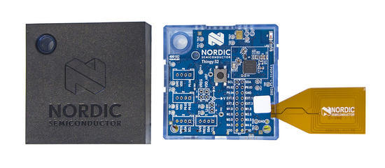
The Nordic Thingy:52 is a 40€/50€ device based on the nRF52832 Nordic microcontroller that has, in a ready to use package, several environmental sensors, that can be accessed by low power Bluetooth (BLE). Nordic provides a complete solution that comprises the Thingy:52 firmware already flashed on the device (Source at GitHub) and an very nice Android Nordic Thingy:52 application, with also sources available at GitHub.
Anyway I have some of these devices for some months now, for other uses, but I decided to test the ESP32 based boards, since the ESP32 has Bluetooth and theoretically can connect and gather gather data from the Thingy. So this post is about the use of the TTGO ESP32 Lora based boards with an OLED to gather data, show it on the OLED, and send it to The Things Network. Seems simple, right?
So when a application connects to the Thingy:52 it can be notified when a sensor value changes throught the standard BLE notification mechanisms. The way the Thingy firmware works, this notification happens at a fixed intervals instead of a value change, and that interval, 5 seconds, 10 seconds, be defined by the Android App or programmatically by our application.
The application is developed by using the PlatformIO and for using the ESP32 Bluetooth interface, I’ve used the NKolban ESP32 BLE Library that happens to be library 1841 at the Platformio repository.
To cut a long story short, as still of today, the ESP32 BLE library doesn’t work correctly with the Thingy:52 notifications. This means that the application subscribes to have notifications, but those never happen. Fortunately someone already hit this problem and solved the issue, but the correction still hasn’t hit the library.
So basically to have my code example to work the following steps are needed:
1. Clone the TTGO ESP32 repository from . The repository uses the PlatformIO to build the application.
2. At the root of the repository run the command pio run so that the libraries are downloaded and installed.
At this point we need to correct the Arduino ESP32 library to add the patch to the notification issue.
Just execute the command:
[pcortex@pcortex:ESP32_NordicThingy|master *]$ cd .piolibsdeps/ESP32\ BLE\ Arduino_ID1841/src
At this directory (.piolibsdeps/ESP32\ BLE\ Arduino_ID1841/src edit the file BLERemoteDescriptor.cpp and at around line 151 (the exact line number will probably change in the future) we must change the ::esp_ble_gattc_write_char_descr function parameters:
/**
 * @brief Write data to the BLE Remote Descriptor.
 * @param [in] data The data to send to the remote descriptor.
 * @param [in] length The length of the data to send.
 * @param [in] response True if we expect a response.
 */
void BLERemoteDescriptor::writeValue(
        uint8_t* data,
        size_t   length,
        bool     response) {
    ESP_LOGD(LOG_TAG, ">> writeValue: %s", toString().c_str());
    // Check to see that we are connected.
    if (!getRemoteCharacteristic()->getRemoteService()->getClient()->isConnected()) {
        ESP_LOGE(LOG_TAG, "Disconnected");
        throw BLEDisconnectedException();
    }

    esp_err_t errRc = ::esp_ble_gattc_write_char_descr(
        m_pRemoteCharacteristic->getRemoteService()->getClient()->getGattcIf(),
        m_pRemoteCharacteristic->getRemoteService()->getClient()->getConnId(),
        getHandle(),
        length,                           // Data length
        data,                             // Data
        ESP_GATT_WRITE_TYPE_NO_RSP,
        ESP_GATT_AUTH_REQ_NONE
    );
    if (errRc != ESP_OK) {
        ESP_LOGE(LOG_TAG, "esp_ble_gattc_write_char_descr: %d", errRc);
    }
    ESP_LOGD(LOG_TAG, "<< writeValue");
} // writeValue
– The ESP32 connects to the Nordic Thingy:52 device.
– It programs the Nordic Device to notify sensor values each 5 seconds (in real use cases it should be much larger period)
– Current sensor data is shown on the serial terminal.
What needs to be done:
– When notified by the Thingy:52, the ESP32 shows the new data on the OLED screen (WIP – Work in progress).
– To keep the application obeying the ISM bands duty cycle, it collects the data, calculates the medium, and sends the data to the Things network each 10 minutes (Also work in progress).
TTN is the The Things Network that provides the required backend services and infra-structure for supporting IoT (Internet of Things) connectivity that uses the LORAWAN protocol.
Anybody can participate on the Things Network by either providing the radio gateways that feed the received data to the TTN backend that, then, delivers it to the user applications, and so increasing the coverage of the TTN network, or just use the network by building TTN Lorawan nodes.
This post is regarding the later case, the build of a simple node based on an Arduino board: the Arduino Micro Pro. So why the Micro PRO, these are quite more expensive than the normal Arduinos, but come in two versions: 5V and 3.3V.
Since I’m using the SX1276 Lora radio that works with 3.3V, I’ve chosen the 3.3V Arduino Pro version so that I do not need to use level shifters if using a 5V based board. Also the Arduino Micro PRO chip, the Atmega32u4 has embedded USB connectivity/port, so no need for serial adapters and/or supporting chips which, at the end, might lead to lower power consumption.
Right now, on sites like eBay and Aliexpress, boards like the Lora32u4 come at least in two versions: with the Atmega328p and with the Atmega32u4. Both suffer the same problem, the Atmel micro processor used only has 32K of RAM available which might be too short to be used for some applications.
This is because the LMIC, the Lorawan stack, takes a huge amount of space if using the original IBM version. A much more memory efficient version for Arduino, originally ported from IBM code, but using a different AES encryption algorithm also exists and saves a lot of memory space. We will see about that. The great advantage of these boards is they also have connection and charger for a LiPo battery, so in reality all we need is to add sensors, battery and our code. An example of such board is the BSFrance Lora32u4 board.
The node build:
While I’m waiting for my Atmega32U4 based Lora32u4 board, I’m using an Hoperf RFM95 radio soldered on board/shield designed for the Wemos ESP8266: Wemos RFM95 Lora shield. this way I can use the RFM radio either on the ESP8266 Wemos based set of boards, or, as in this case, with the Arduino 32u4.
The Hallard shield as one interesting feature that is that merges all the Lora transceiver status pins by using diodes and hence only use one Arduino pin for inquiring Lora SX1276 radio status. This is needed due to the lack of I/O pins on the Wemos ESP8266 board. For this to work on Arduino we need to add a pull-down resistor to the Arduino pin that connects to the merged output. In my case I used a 10K resistor.
The RFM95 radio is controlled using SPI, so we need to use also the SPI Arduino Pins, and also need to connect the Chip Select pin.
The schematics is as follows:
Arduino Pro Micro and RFM95 Wemos Shield
The node software:
After the node hardware build is done, from the software perspective the node needs now at least another two things: the LMIC stack for implementing the Lorawan protocol support over the Lora radio and, at the TTN site, the device configuration.
Since I’m using Platformio to develop, the LMIC library is the library 852: pio lib show 852. We need to install it and add the reference to it on the file platformio.ini. Also since there is no ATMega 32U4 board on the Platformio IDE available boards, we can use the Adafruit Feather 32u4 board, which is the same thing:
The device registration can be done so that the node device access the TTN network in two different ways:
ABP – Activation by personalisation – This means that all set of keys required to join the Lorawan network are embedded into the software.
OTAA – Over the Air Activation – The network session keys needed to join the Lorawan network are generated when the device tries to join the network.
On this post we will ABP first, since I have no nearby TTN gateway capable o OTTA (I’m using a single channel gateway without downlink support.).
Anyway, the node code is really nothing special, except the necessary configuration for the LMIC to communicate with our RFM95 board.
On the ABP device registration TTN page we need to register our device, so that, on main.cpp code file we can fill the required keys and device ID.
As a quick introduction, after registering onto the TTN site, we go to the console and choose Applications. We can there create or reuse an existing application and register the device, making sure we choose ABP as the method to join the network.
On the Device EUI field, either we fill it or press the crossing arrows to generate an ID. We let the system generate an ID, and then we can finally press the Register button.
The newly register device is configured as an OTAA device:
So we go to Settings and change the OTAA to ABP. After this step we have the required data to put on our code.
Since our node doesn’t have any memory to track frame counting that survives reboots or power cycles, we disable the frame counter checks.
Don’t forget to press save. Again on the main device screen we can now copy the keys to the code:
We can now copy the keys:
static u1_t NWKSKEY[16] = { 0xEE, ... ... ... ... }; // <- Put here the NETWORK KEY
static u1_t APPSKEY[16] = { 0x4E, 0x12, ... ... ... ... };  // <- Put here the APPLICATION KEY
static u4_t DEVADDR = 0x26304050;   // Put here the device id in hexadecimal form.
Testing:
Compiling the code with the pio run command, we have the following output when using the original IBM LMIC library:
And we can flash the firmware with the command: pio run -t upload.
The result is data on the TTN console referring to our device:
The problem… :
So, everything runs OK, and we can send data to the TTN Network, everything looks good, right?
As soon we start to add functionality to our code, for example reading some I2C sensors, our some serial debug messages, we hit this problem:
Linking .pioenvs/feather32u4/firmware.elf
Checking program size
text       data     bss     dec     hex filename
Error: The program size (28756 bytes) is greater than maximum allowed (28672 bytes)
28548       208     749   29505    7341 .pioenvs/feather32u4/firmware.elf
*** [.pioenvs/feather32u4/firmware.elf] Explicit exit, status 1
So in reality we can’t add much functionality to our code if using a full LMIC stack, since it occupies a lot of the available flash memory.
Trimming down the IBM LMIC stack:
Since our node is ABP only we can strip out some LMIC functionality for OTAA an other Lorawan features. For this we need to edit the config.h file from the LMIC library. Since we are using platformio, this file is located at project_root/.piolibdeps/IBM LMIC framework_ID852/src/lmic
We only leave support for ABP by enabling the disable lines for other LMIC functionality:
...
...
// Any runtime assertion failures are printed to this serial port (or
// any other Print object). If this is unset, any failures just silently
// halt execution.
#define LMIC_FAILURE_TO Serial

// Uncomment this to disable all code related to joining
#define DISABLE_JOIN
// Uncomment this to disable all code related to ping
#define DISABLE_PING
// Uncomment this to disable all code related to beacon tracking.
// Requires ping to be disabled too
#define DISABLE_BEACONS

// Uncomment these to disable the corresponding MAC commands.
// Class A
//#define DISABLE_MCMD_DCAP_REQ // duty cycle cap
//#define DISABLE_MCMD_DN2P_SET // 2nd DN window param
//#define DISABLE_MCMD_SNCH_REQ // set new channel
// Class B
#define DISABLE_MCMD_PING_SET // set ping freq, automatically disabled by DISABLE_PING
#define DISABLE_MCMD_BCNI_ANS // next beacon start, automatical disabled by DISABLE_BEACON
By uncommenting the above lines, our code now takes (we can and should ignore the LMIC compile warnings):
Conclusion:
The availability of boards with the AtMega32u4 processor, Lora Radio and LiPo charge and battery connectivity, is a great step to start using the TTN (or other) Lorawan networks. But with only with 32K or flash memory, for some applications, these boards might not be the best solution.
Also the price for such boards are still a bit on the expensive side, since a discrete 32u4 + RFM95 + Lipo charger is a bit cheaper than the single board solution.
Anyway, the STM32F103 blue pill boards cost half of the 32U4 price and have double the flash size and 9x the clock, are also 3.3v compatible and so it would be great that such single Lora boards used the STM32F103 instead of the 328p or 32u4…
So my conclusion is, without power considerations taken into account, a STM32F103 + RFM95 and LiPo charger, is a better alternative than the one that I’ve used here.
RSMB: Really Small Message Broker is an MQTT broker/server, simpler than the alternatives like Mosquitto, RabiitMQ, and so on. While it has its origins in IBM labs (as the MQTT protocol), it is now a project/sub project on Eclipse Paho MQTT related software. While downloading the RSBM does provide some binaries for some common platforms, it doesn’t offer any binaries for, in my case, the DS212+ Marvell 88F628x ARM processor.
So let’s see how to cross compile the RSMB for Synology DS and in this process also learn how to cross compile in your desktop computer native software for the Diskstation.
Requirements:
Linux Desktop. This WILL make everything simpler. Sorry can’t provide information for Windows.
Uncompress the file into the /usr/local directory. DO USE this directory. The tool chain is configured to get all files, libraries and so on from the /usr/local/… directory:
sudo tar xvzf gcc464_glibc215_88f6281-GPL.tgz -C /usr/local/
(Note: It’s a CAPITAL C. Check Synology documentation).
Access through ssh the Synology terminal, and make sure that broker is executable and do a test run:
cd /usr/local/bin
chmod +x broker
./broker
20150104 190523.162 CWNAN9999I Really Small Message Broker
20150104 190523.162 CWNAN9998I Part of Project Mosquitto in Eclipse
(http://projects.eclipse.org/projects/technology.mosquitto)
20150104 190523.163 CWNAN0053I Version 1.3.0.2, Jan  2 2015 20:13:39
20150104 190523.163 CWNAN0054I Features included: bridge
20150104 190523.163 CWNAN9993I Authors: Ian Craggs (icraggs@uk.ibm.com), Nicholas O'Leary
20150104 190523.163 CWNAN0014I MQTT protocol starting, listening on port 1883
For configuring the RSMB, we really should really read the documentation… 🙂 that is provided…
A simple configuration file should be located at /usr/local/etc and named rsmb.conf with the following basic contents:
# sample configuration on port 1883 with retained persistence in /tmp
port 1883
max_inflight_messages 50
max_queued_messages 200
persistence_location /tmp/
retained_persistence true
And at the /usr/local/etc/rc.d create a file named S99rsmb.sh with the following content:
#!/bin/sh

case $1 in
start)
    nohup /usr/local/bin/broker /usr/local/etc/rsmb.conf >> /var/log/rsmb.log&
    /usr/bin/logger -p1 -t "rsmb: INFO  " " Service started."
;;
stop)
    /usr/bin/killall broker
    /usr/bin/logger -p1 -t "rsmb: INFO  " " Service stopped."
;;
esac
Save and chmod +x S99rsmb.sh
Now the broker should start and stop automatically.
Final notes:
To use the broker from the Internet the port 1883/TCP should be open/forward at your router/firewall, and you should add authentication to the MQTT broker.