It is a long time since I’ve written something on the blog, but anyway, a quick note regarding to how to transform a C float type (float myvar;) to float in NodeJs (float32).
We might need this transformation when processing incoming float data from somewhere running a C based code to a NodeJs based backend. For example capturing IMU data in a bluetooth device running a C based firmware, then sending the data to a NodeJS backend.
Basically in C, a float type is a four byte sized variable that has a mantissa and an exponent.
So in the first case we send a single float, and on the last case an array of three floats.
For the NodeJs side, the following function retrieves back the floats directly into an array, either with one position, for the single var, or with three positions for the three floats array:
function bufferToFloat32Array(buffer) {
    let arr = [];
    const size = Float32Array.BYTES_PER_ELEMENT;
    for (let i = 0; i < buffer.length / size; i++)
      arr.push(buffer.readFloatLE(i * size));
    return arr;
  }
And that is it. A complete example is as following:
As show on my previous posts, it is possible to implement an OpenThread (OT) network that uses an ESP32 with a NRF52840 dongle to implement an OpenThread Border Router (OTBR) instead of using the ESP32-H2 as the radio module. Nevertheless the main difference regarding the documented instructions for building a Border Router that uses a RPi and the ESP32 based implementation is that RPi can also provide NAT64 services and DNS64 services. These services allow the OT network, that only uses IPv6, to access and communicate with “standard” IPv4 networks and services.
On previous firmware versions for the ESP32 based Border Router, those services where not offered, and hence, from the OpenThread network, it was only possible to access external services that already had IPv6 addresses or either by deploying NAT64 and DNS64 as external services, in which case, allowed for IPv4 services and networks to be accessed.
Currently, at least now on the ESP-IDF development framework commits from September 26 (commit 02605f1a31be4… and above) of the main branch, the ESP32 OTBR already offers NAT64 services, but no DNS64 services.
Anyway let’s see how implementing NAT64, either externally or using the native ESP32 NAT64 support, and DNS64 can allow OT devices to access and use IPv4 based services.
Brief introduction to NAT64:
So what is NAT64 (Network Address Translation IPv6/IPv4) ? NAT64 is the mechanism that allows address translation from IPv6 addressing, used on the OpenThread Network, to the LAN and WAN/Internet IPv4 version. As such NAT64 allows OpenThread IPv6 devices to access IPv4 services/servers that only have IPv4 addresses. Notice that standard NAT (NAT44) applies to IPv4 to IPv4 translation while NAT64 applies to IPv6 to IPv4.
The NAT64 mechanism is not mandatory, for example if the LAN already has a IPv6 addressing configured and all the services expected to be used by the OpenThread devices are local on that IPv6 network. In reality this is mostly the case since starting up OTBR will broadcast a RA (Router Announcement Advertisement) on the network, and through SLAAC all the machines will have an IPv6 directly accessible from the OT network.
Nevertheless, if we want our OpenThread devices to access any Internet service/servers, the situation is a bit more complicated: While a lot of Internet services already are available on IPv6, to able to access them directly from the OpenThread Network requires that the LAN (to which the OTBR is connected) has a valid public IPv6 prefix/address space assigned (this also be not be the case if there is NAT66 on the network which is also not a good thing to have…). Also in addition, it is also required that the Internet Provider is able to route (and configure the access router) correctly to allow connectivity to our IPv6 network that uses public addressing. In short it is a bit more complicated and requires more than basic IPv6 skills…
Anyway, the key aspect to keep, is that if we want to access an IPv4 service/server or the Internet (or on the local network) with minimal complications from the OpenThread network, NAT64 is required to be able to do such access.
Brief introduction to DNS64:
The DNS64 service comes as a consequence of NAT64 mechanism. On an OpenThread networks with devices that only use IPv6 addresses, if a OT device does a DNS query such as: What is Google DNS IP address? what it should be returned? One of the Google IPv4 addresses such 8.8.8.8 or one of the IPv6 addresses such as 2001:4860:4860:0:0:0:0:8888? The answer is that it should be the later, not the former, since OpenThread nodes do not support IPv4. But to be able to query Googles IPv6 DNS directly means that the nodes and all its infrastructure is able to access directly (not through NAT64) the internet by using IPv6.
So to keep this simple, all DNS queries from a OpenThread node should return an IPv6 address, and this is OK if: 1) we can access the Internet directly through IPv6 and 2) the DNS server for the query can return an IPv6 address (an AAAA DNS address record).
This might not work (and in most cases doesn’t…) because in most cases we don’t have a valid IPv6 network for our LAN AND we might need to access an Internet Service that only has IPv4 address and no AAAA record.
DNS64 solves this issue, by providing a local DNS server that can receive queries for AAAA IPv6 records from the OpenThread devices, transform them into A IPv4 queries to a upstream DNS IPv4 server (such as Google’s 8.8.8.8), and relaying back the answer with the IPv4 address transformed into a IPv6 address to the node that made the query.
The question is to transform the IPv4 address into a IPv6 address for answering the DNS query how can it be done? The answer is that for this to work DNS64 must work in conjunction with NAT64.
NAT64 and DNS64 working together:
NAT64 works by using a IPv6 network prefix that is configured to accept any network connection to that prefix and then “NATs” it to the IPv4 address. For example, if the NAT64 prefix is 64:ff9b::/96, then if the OpenThread node tries to connect to 64::ff9b::808:808 (8.8.8.8 IPv4 address encoded in IPv6 format. We can also use 64::ff9b::8.8.8.8) the connection goes through the NAT64 server where the prefix is removed leaving only the IPv4 part (8.8.8.8) and since we are now in IPv4 address space, the rest works as expected (including probably NAT44 again at our Internet Provider router!). On returning the reverse happens where the answer goes back to the node from the 8.8.8.8 transformed back again into 64::ff9b::808:808.
So any time a OpenThread node wants to contact a IPv4 address, either internal or external, just adding the NAT64 prefix 64:ff9b::/96 will route the request through NAT64.
To solve our previous problem of transforming a DNS answer A record into a AAAA record, DNS64 works side by side with NAT64 and the configured NAT64 prefix. It does this by first transforming any query for AAAA records to A records, and transforming the answers from A records back to AAAA records by adding the NAT64 prefix to the A answer.
For example, lets suppose that a OT node has Google DNS configured but access it using NAT64, hence configured DNS server is 64::ff9b::808:808. If the node does a DNS query through NAT64 to Google, what is the IP address of, for example, http://www.xyz.otn that is returned?
Two cases can happen: 1st) if http://www.xyz.otn has only an IPv4 address (let’s suppose its 10.20.30.40) and it has no AAAA IPv6 address, then this means that the DNS server cannot answer the OT node query since OT nodes only asks for IPv6 AAAA records. 2nd) if http://www.xyz.otn does have a AAAA IPv6 record, it is a public Internet address, and so, the DNS query does return a valid IPv6 address, but might not be usable since the node can not access the Internet directly through IPv6.
Now, let’s suppose a local Linux machine is running DNS64 (and probably also NAT64). If the node uses our local DNS64 as the DNS server and queries for http://www.xyz.otnAAAA IPv6 address record, the DNS64 server will transform the IPv6 AAAA request into a IPv4 A address query. The DNS query for the A record is then sent to the upstream DNS server, receives the answer but before relaying the DNS response to the OT node, it transforms the IPv4 answered address 10.20.30.40 into a AAAA IPv6 record answer with address 64::ff9b::10.20.30.40 by adding the NAT64 prefix!
We can see now that node with this address can contact the http://www.xyz.otn through NAT64 since the DNS64 answer added the NAT64 prefix to the IPv4 address and as such all works as expected.
Next steps:
This post is getting rather long, but at least the necessary stepping stones for understanding (I hope) how OpenThread Networks integrate with NAT64 and DNS64.
On Part II of this post, deploying NAT64 and DNS64 services on a Linux machine and execute testing to check network connectivity through the deployed services is carried out.
FreeRtos real time operating system can be used in conjunction with the Arduino STM32 framework by importing the Stm32duino FreeRtos library, namely if using PlatformIO, by defining the dependency on the platformio.ini file at the project root:
lib_deps = stm32duino/STM32duino FreeRTOS
From this point on it is possible to use the FreeRTOS capabilities, while being able to leverage the large availability of other Arduino libraries.
Nevertheless while testing some of the examples of STM32duino FreeRTOS, such as the blink example, it just didn’t work. The board after starting just hanged and nothing happened: No blinking led…
One key aspect, and the root for this issue, is that the example uses the Serial.begin() function to serial output some messages to the user, but specifically, in my case, since I’m using platformio, I’ve enabled on the platform.ini file the serial output to be redirected to USB instead of standard serial port:
These entries are require to enable STM32 USB output from the ARduino framework Serial commands.
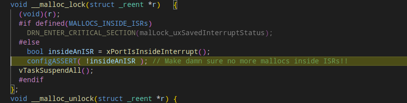
Starting a debug session, to see why or where the code is stuck, we get that the code is stopped in the following assert:
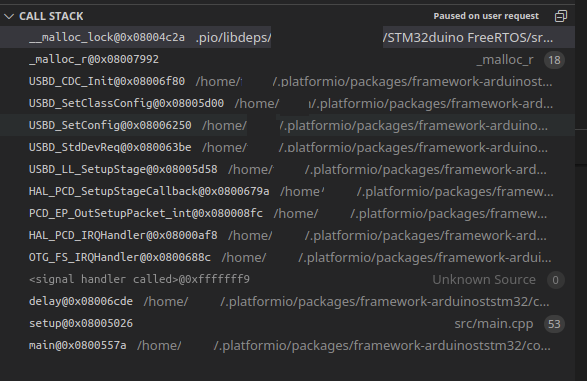
Checking the stack trace, we have:
Ok, so it seems that malloc function is getting called from an ISR, specifically the USBD_CDC_Init function:
And that’s it seems to trigger the ASSERT and hence the failure.
But if we remove, from the platform.ini file, the USB related configuration options that enables USB, namely the -D PIO_FRAMEWORK_ARDUINO_ENABLE_CDC, then everything just works fine.
So how we can have Arduino, FreeRTOS and still use USB on STM32 when using Platformio?
The solution is quite simple, and is a bit hidden in the internet since it seems not many people are using this combination of STM32, Arduino, FreeRTOS and USB. We only need to change the Heap memory manager to be used by the code by defining FreeRTOS to use the heap_3 management policy/configuration:
With this change, now everything works as supposed.
Edit: What this change on the Heap Management means is that FreeRTOS will use now the standard C memory management functions, and not the specific ones that bring the issue, and hence it works as expected. Anyway, for some use cases, the selection of this heap management might not be ideal, but it is a tradeoff to be able to used the USB port as an output and input serial console.
This is just a short post to help out those might come across the same issues:
Alternate I2C pins
Standard I/O pins on the STM32 range of micro controllers might handle several functions, depending how it is configured. CubeMX from ST allows to see what functions a pin might have.
Now specifically for I2C, for example I2C1 (bus 1 of I2C) the default pins on a STM32F411 are PB6 and PB7 for SCLK and SDA. So there is no need to do anything when using the default pins on I2C1.
But on some boards, the I2C1 bus might be using other pins, so before initializing the bus, we need to set them.
For example, a CubeMX allowed configuration for I2C1 on a STM32F4xx processor is using PB10 and PB9 for SCLK and SDA, and the following code initializes the bus with those pins:
But this won’t work because for PB9, the SDA is an alternate function, and not a generic I/O function and so to correctly initialize the bus we need to use the alternate function of PB9 with PB9_ALT.
Alternate pins and their usage can be checked on the processor datasheet.
So, if initializing a I2C bus, a SPI bus or an UART with specific pins and it is not working, it is better to check if the pins definitions must be changed to use the _ALT posfix.
STM32 SH1106 OLed driver for Arduino:
Finally, on the follow up about the I2C bus configuration, if connecting a I2C OLed screen that is using the SH1106 driver instead of the more common ssd1306, I’ve created a repository on Github based on the Adafruit library for the ssd1306, modified by wonho-maker to support the SH1106 and still be compatible with other Adafruit libraries (such GFX), that can compile with the Arduino STM32 framework, and so, be used on STM32 based boards.
I’ve tested the library on a STM32F411 WeAct blackpill board and with a 1.3′ Diymore OLed, and it works as the original Adafruit library for the ssd1306.
Since I do not own a NRF52840-DK (Development Kit) with integrated debug interface, I do my programming and tests on the NRF52840 dongle by uploading firmware through the DFU mode (by pressing the lateral reset button) by using the nrfutil-linux utility. Also since the dongle has no debug interface, most of the debugging is done through console output but this is not enough for more complex developments such as using Zephyr RTOS.
The adapter board is a 1.27mm 10 pin adapter to a 20 2.54mm pin adapter such as this:
JTAG adapter for different pin pitches.
Anyway I had laying around a NRF52840 dongle, with the SWD header already soldered that didn’t respond to any interaction. Plugging it in the led’s flashed rapidly and then went off, and the DFU mode didn’t work. Is it dead?
Well, fortunately no. Connecting to the dongle with the JLink JTAG probe, after the connection we can see that the NRF52840 chip is alive, and so it is probably running some weird firmware (that I can’t remember what it was for) that wipped out the original factory firmware that allowed DFU to work.
So running the command: ./JLinkExe -if SWD -device NRF52 -speed 4000 we can see that after the connect command there is a response:
SEGGER J-Link Commander V7.70e (Compiled Aug 31 2022 17:11:43)
DLL version V7.70e, compiled Aug 31 2022 17:11:20

Connecting to J-Link via USB...O.K.
Firmware: J-Link V10 compiled Jul 22 2022 11:40:29
Hardware version: V10.10
J-Link uptime (since boot): N/A (Not supported by this model)
S/N: 5011____
License(s): GDB
VTref=2.980V

Type "connect" to establish a target connection, '?' for help

J-Link> connect
Device "NRF52" selected.

Connecting to target via SWD
InitTarget() start
InitTarget() end
Found SW-DP with ID 0x2BA01477
DPIDR: 0x2BA01477
CoreSight SoC-400 or earlier
Scanning AP map to find all available APs
AP[2]: Stopped AP scan as end of AP map has been reached
AP[0]: AHB-AP (IDR: 0x24770011)
AP[1]: JTAG-AP (IDR: 0x02880000)
Iterating through AP map to find AHB-AP to use
AP[0]: Core found
AP[0]: AHB-AP ROM base: 0xE00FF000
CPUID register: 0x410FC241. Implementer code: 0x41 (ARM)
Found Cortex-M4 r0p1, Little endian.
FPUnit: 6 code (BP) slots and 2 literal slots
CoreSight components:
ROMTbl[0] @ E00FF000
[0][0]: E000E000 CID B105E00D PID 000BB00C SCS-M7
[0][1]: E0001000 CID B105E00D PID 003BB002 DWT
[0][2]: E0002000 CID B105E00D PID 002BB003 FPB
[0][3]: E0000000 CID B105E00D PID 003BB001 ITM
[0][4]: E0040000 CID B105900D PID 000BB9A1 TPIU
[0][5]: E0041000 CID B105900D PID 000BB925 ETM
Cortex-M4 identified.
J-Link>_
So we’re good to go. All we need is to find the original factory firmware, and after some search, the firmware named graviton_bootloader_mbr_v1.0.1-\[nRF5_SDK_15.0.1-1.alpha_f76d012\].hex was found on the Nordic site (the forums) and downloaded. There is a Nordic Blog Post that explains all is needed to do at https://devzone.nordicsemi.com/guides/short-range-guides/b/getting-started/posts/nrf52840-dongle-programming-tutorial, and where the Dongle factory firmware can be downloaded from the section Revert to production bootloader.
Since we can now connect to the dongle through the JLink probe, we exit the JLinkEXE command, and using the nrfjprog tool (in my case for Linux) we need to erase whatever is on the dongle and program it:
Erasing the old firmware:

# ./nrfjprog -e
Erasing user available code and UICR flash areas.
Applying system reset.
DO NOT RESET OR DISCONNECT the dongle here, since the UICR is now not programmed (which controls the dongle voltages). We need to flash immediately the firmware:
Writing the factory firmware:

# ./nrfjprog --program ~/Downloads/graviton_bootloader_mbr_v1.0.1-\[nRF5_SDK_15.0.1-1.alpha_f76d012\].hex --reset --log
Parsing image file.
WARNING: A programming operation has been performed without --verify.
WARNING: Programming can fail without error.
Applying system reset.
Run.
And that’s it, the dongle booted up straight to DFU mode (the breathing red led) and could be flashed again.
One of my mistakes regarding the previous post building an ESP32 based OpenThread Border Router was not tracking which commit version from the esp-idf repository I was using along on my tests. As I moved along in testing the border router and finding that some functionality was not working as expected, I’ve rebuild the ot_br esp-idf example by updating the esp-idf to the latest commit. This in fact turned into a disaster since the latest commits are not stable for OpenThread use…
So, without further ado, let’s see how we can, more or less build a stable ESP32 OTBR.
The NRF52840 RCP
After searching some of the issues on the esp-idf repository, it seems that EspressIf is using the ot-nrf528xx repository but NOT on the head commit but on a specific commit: 8c508c8b693ce660134e934c967835cb43ffcc31
This was more or less inferred from this esp-idf github issue, so is not from any official documentation… Also in the same post a specific esp-id commit is also referred…
So to build the NRF52840 dongle based OpenThread radio, we need to do the following:
And from this point we can follow compile the RCP for the NRF52840 which will compile to the RCP API version 5.
We should now edit the transport-config.h file on the nrf52840 directory to define the necessary UART parameters (pins and flow control) to match what the ESP32 OTBR is expecting:
# cd src/nrf52840
# vi transport-config.h               <- Use your preferred editor....
The UART configuration looks like (changes in bold):
Basically Hardware flow control was disabled, the TX and RX pins where changed to a set of pins on the dongle that definitely work, and I’ve moved out also the CTS and RTS pins.
To compile, we go back to the repository root and execute:
Note that I’m using the nrfutil-linux utility version because the nrfutil version on Arch Linux is broken. If using other Linux versions, like Ubuntu (not tested) nrfutil might work just fine.
And that’s it, the NRF52840 dongle with RCP version 5 is ready and uses the same pins as the previous post.
The ESP32 Border Router
While the RCP itself didn’t gave much trouble by using the Nordic Connect SDK version of it, the Border Router did have some issues.
The major issue was regarding to the Thread Network routing. The issue was that the OMR (off-mesh routing prefix) was not advertised through IPv6 Router Advertisement (RAs) ICMPv6 packets. In fact I had two situations:
In specific esp-idf commits, the initial RAs was sent, but only that one. This meant that some host computer did know the OTBR presence on the network when it booted up, but since the OTBR didn’t refreshed the route (it didn’t send any periodic RAs), the hosts, after sometime, removed the expired routes. This also meant if the hosts rebooted after the router has booted, the OTBR and the thread network would be unknown to them.
In the actual esp-idf commit ( c2ccc383dae2a47c2c2dc8c7ad78175a3fd11361 – late June 2022) no RAs are sent at all… So no way, without static routing configuration to access the thread network.
A serious of issues where solved on the esp-idf commit id https://github.com/espressif/esp-idf/commit/495d35949d50033ebcb89def98f107aa267388c0 which solved the issue with the no Router Advertisements and an overflow timer, so this commits works better than the previous one which after an hour stop advertising the mesh prefix and routes.
The above issues do not happen at least at specific commit recommended by an Espressif employee.
So, to compile the ot_br example to a more or less stable version of it, the following steps must be done (NOTE: Any previous espressif installation needs to be removed! including the .espressif folder where tools are located.)
# echo "Do this if you know what you are doing!"
# rm -rf ~/.espressif
# rm -rf esp-idf
# git clone https://github.com/espressif/esp-idf.git
# cd esp-idf
# git checkout daa950d9ed1cc3cdc85c09b14ddfeb68a2ac6674
# git submodule update --init --recursive
# ./install.sh
# . ./export.sh
And all should be fine now, at least for basic IPv6 connectivity between hosts and the thread nodes.
We can check the local linux routing table with the route -6n command, and also use ping to check basic connectivity.
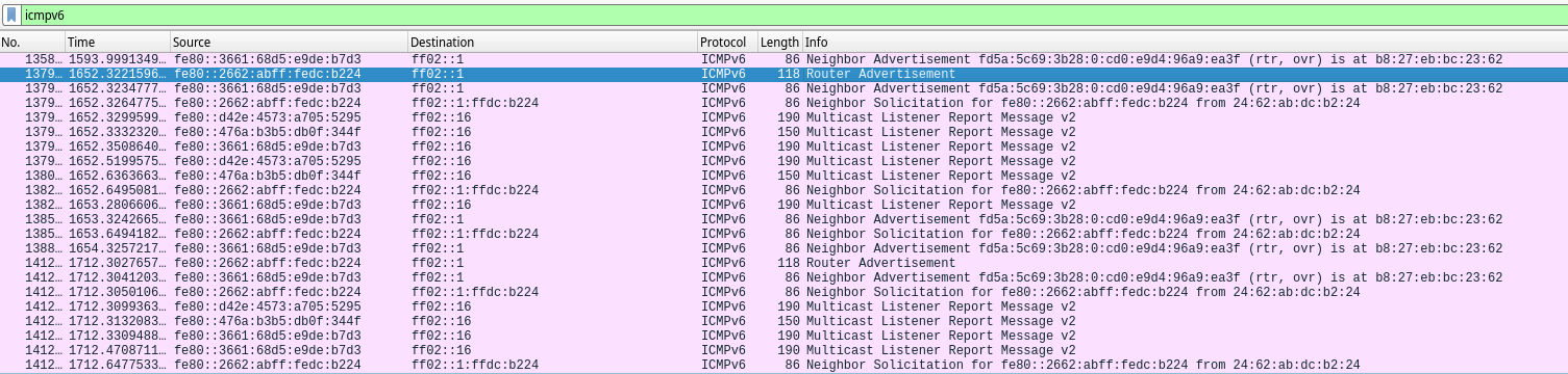
Running wireshark on a host, we can see now the periodic IPv6 Router Advertisements and can ping directly any thread node, send coap messages and so on.
Wireshark capture of ESP32 BR Router Advertisements
Some final thoughts
The ESP32 based Border router does indeed provide the basic functionality without incurring on the more expensive and complex based border routers using the RPi, for example. No OS to cater for, no SD cards, log files and so on, so a more simple approach to get Network <-> Thread connectivity.
Still I have some issues with this commit, for example, if the WIFI disconnects and then connects again the Border Router does not recover (regarding the IPv6 network management). It still says it is connect but meanwhile the BR stops any periodic router advertisements.
Also I still haven’t tested any external device commissioning using for example the commissioner-cli tool or the Android Thread App, but the Thread App finds the ESP32 border router without any problem.
Openthread is a 802.15.4 radio mesh network that uses IPv6 as the network protocol to communicate between other nodes but also to communicate with the outside world. The Border Router (BR) is the network component that allows OpenThread nodes to access the external networks and vice-versa. And yes, due to the native use of IPv6 we can access our node directly from across the world (if we wish so) directly!. So a Border Router in a OpenThread network is much like a standard router that routes packets between the Openthread radio network to our network or the internet. No application layer conversion whatsoever, just standard IPv6 networking.
A common way to build an OpenThread Border Router is to use a Raspberry Pi (3 or 4) and a 802.15.4 radio to connect to the OpenThread network. A common device used for this is the Nordic NRF52840 chip that is capable of BLE and 802.15.4. The NRF5240 PCA10059 dongle due to its small dimensions (unlike the NRF52840 development kit) is a common device used as the radio componente in building the Border Router.
But the RPI/Dongle combo, while easier to build specifically with docker support , has some drawbacks, namely first to be able to buy a RPI now (…), SD card life time (if not using eEMC disks or external disks), power consumption, among others. So it was with interest that on the Espressif announcement of the ESP32-H2 the Thread protocol, part of the OpenThread project is supported. More so, on the the OpenThread official site an ESP32 based Border Router was documented!
So the question was, could an ESP32 module work with an NRF52840 dongle, instead of the ESP32-H2 (that as far that I know are not yet available), work as the radio for building a Border Router? The short answer is yes! It does indeed work, bridging the OpenThread network through the ESP32 Wifi interface to our network and to the internet.
The OpenThread coprocessor is the software that runs on the radio enabled chip that connects to the OpenThread network.
There are two types of coprocessors, the NCP: Network Co-Processor, and the RCP: Radio Co-Processor. The difference is explained on the Openthread site with great detail, but the key point is that the ESP32 will only work with an RCP, not an NCP. So we need to program the NRF52840 dongle with a RCP firmware.
Second, RCP offers an API, and this API can be version 4, 5 and so on. At the moment, the ESP32 Border Router only allows the RCP api version 4 or 5, not 6 which is the latest.
Finally, the NRF52840 dongle when used as the RCP on the RPi based Border Router uses the USB connection as the medium for the serial communication with the RCP. With the ESP32 we want to use a standard UART so we can connect the UART pins from the dongle to the ESP32.
With this in mind, let’s see how to build and flash the RCP.
Building and flashing the RCP
There are at least three sources from where we can build and then flash the RCP on the NRF52840 dongle:
The Nordic ot-nrf528xx Git repository. This will build RCP (that I use with the RPi) that can use the USB or UART connection. Unfortunately I wasn’t able to make it using UART (but I didn’t investigate much), so I’ll will try in the future, but for now is in standby. (I was able to make the UART to work (it was the pins…), but the RCP API is version6, see below).
The Nordic RTOS coprocessor example (is the same one as the Zephyr RTOS) but on the Nordic Connect SDK.
The main difference between the Zephyr RTOS version and the Nordic one is that Zephyr, if using the latest commit, will create a RCP using RCP API version 6. Nordic on the other hand, if using version 1.9, that uses Zephyr 2.7 will create RCP that uses RCP API version 5. And this one will work with our ESP32 based border router.
Anyway, attention must be taken to which Zephyr RTOS version is being used, and in my case I ended up using Nordic Connect SDK 1.9.1 which uses Zephyr 2.7.99, because my main Zephyr repository in my PC was already on the latest commit (3.0.99), and I didn’t want to go back…
Anyway, with Zephyr is simple to compile the RCP coprocessor using the UART instead of the USB connection.
Now on the coprocessor sample location ( ???/???/zephyr/samples/net/openthread/coprocessor), we just need to create an overlay file named nrf52840dongle_nrf52840.overlay and put it on the boards directory with the following contents:
/ {
    chosen {
        zephyr,ot-uart = &uart0;
    };
};

/ {
    /*
    * In some default configurations within the nRF Connect SDK,
    * e.g. on nRF52840, the chosen zephyr,entropy node is &cryptocell.
    * This devicetree overlay ensures that default is overridden wherever it
    * is set, as this application uses the RNG node for entropy exclusively.
    */
    chosen {
        zephyr,entropy = &rng;
    };
};
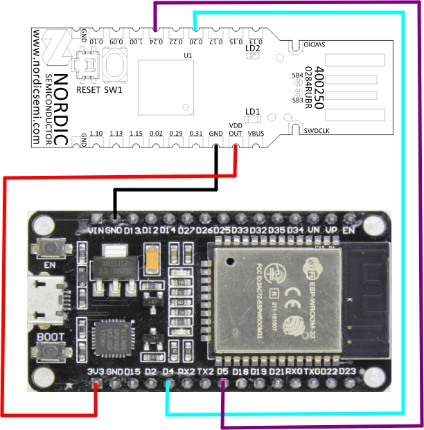
As we can see all that was needed was to define the OpenThread communications UART to use a real UART port, in this case uart0. If we go to the DTS file that specifies the hardware for the dongle we can see that uart0 uses the following pins:
TX Pin: 20
RX Pin: 24
The ESP32 will use pins D4 for RX and D5 for TX, so we need to connect NRF Pin 20 to ESP32 Pin D4 e NRF Pin 24 to ESP32 pin D5. Also notice that this overlay will NOT use hardware flow control since it is not specified on the DTS and neither on our overlay file.
Now we can just compile (your Nordic Connect SDK must be correctly configured…):
west build -p always -b nrf52840dongle_nrf52840 -- -DOVERLAY_CONFIG="overlay-rcp.conf" -DCONFIG_OPENTHREAD_THREAD_VERSION_1_2=y
And we can flash it now on the dongle. We need to put it on DFU mode by pressing the lateral reset button and waiting for the breathing red led:
Notice that I use nrfutil-linux because the “normal” nrfutil in Arch Linux doesn’t work due to Python versions.
And that’s is, the RCP is done, all that is missing is to connect it to the ESP32, and power it up.
In my test I’m using a standard off the shelf ESP32 development board, and I provide the dongle +3.3v from the ESP32 3.3v pin to the dongle Vout pin (yes, it is Vout.), which means that by powering up the ESP32 through USB I also power up the dongle.
The ESP32 Border Router
All we need now is to flash the ESP32 with the sample border Router. For that we need the latest ESP-IDF SDK to flash the code.
After everything is installed and after running the . ./export.sh script o the esp-idf root directory we can go to examples/openthread/ot_br and compile the Border Router and flash it.
And that’s it, we should have a working Border Router.
Checking it out
After boot we have the following output from the ESP32:
I (0) cpu_start: App cpu up.
I (621) cpu_start: Pro cpu start user code
I (621) cpu_start: cpu freq: 160000000 Hz
I (621) cpu_start: Application information:
I (626) cpu_start: Project name:     esp_ot_br
I (631) cpu_start: App version:      v5.0-dev-2959-g31b7694551-dirty
I (638) cpu_start: Compile time:     May 21 2022 18:09:20
I (644) cpu_start: ELF file SHA256:  404095e613551c1d...
I (650) cpu_start: ESP-IDF:          v5.0-dev-2959-g31b7694551-dirty
I (658) heap_init: Initializing. RAM available for dynamic allocation:
I (665) heap_init: At 3FFAE6E0 len 00001920 (6 KiB): DRAM
I (671) heap_init: At 3FFC0F08 len 0001F0F8 (124 KiB): DRAM
I (677) heap_init: At 3FFE0440 len 00003AE0 (14 KiB): D/IRAM
I (683) heap_init: At 3FFE4350 len 0001BCB0 (111 KiB): D/IRAM
I (690) heap_init: At 40095BC8 len 0000A438 (41 KiB): IRAM
I (697) spi_flash: detected chip: generic
I (701) spi_flash: flash io: dio
I (706) cpu_start: Starting scheduler on PRO CPU.
I (0) cpu_start: Starting scheduler on APP CPU.
I(808) OPENTHREAD:[I] Platform------: RCP reset: RESET_POWER_ON
I(838) OPENTHREAD:[N] Platform------: RCP API Version: 5
I (958) OPENTHREAD: OpenThread attached to netif
Notice that the RCP version is 5, which means we are able to communicate with the RCP throught the UART.
We are set. So we need now to start things up, by connecting to wifi:
> wifi connect -s my_ssid -p my password
...
...
I (127298) esp_netif_handlers: sta ip: 192.168.1.153, mask: 255.255.255.0, gw: 192.168.1.1
I(127798) OPENTHREAD:[N] BorderRouter--: No valid OMR prefix found in settings, generating new one
I(127818) OPENTHREAD:[N] BorderRouter--: Local OMR prefix: fd55:91ab:2b5a:5186::/64 (generated)
I(127818) OPENTHREAD:[N] BorderRouter--: Local on-link prefix: fdad:ed43:b217:0::/64 (generated)
We have now our OMR prefix (Off mesh prefix), on another words the network address that our mesh network will be known from the outside. So we need to bring the network interface up, and start OpenThread:
> ifconfig up
I (279898) OPENTHREAD: Platform UDP bound to port 49153
Done
I (279898) OPENTHREAD: netif up
> thread start
I(284758) OPENTHREAD:[N] Mle-----------: Role disabled -> detached
Done
> I(285448) OPENTHREAD:[N] Mle-----------: Attempt to attach - attempt 1, any-partition
I(287488) OPENTHREAD:[N] RouterTable---: Allocate router id 44
I(287488) OPENTHREAD:[N] Mle-----------: RLOC16 fffe -> b000
I(287498) OPENTHREAD:[N] Mle-----------: Role detached -> leader
I(287508) OPENTHREAD:[N] Mle-----------: Leader partition id 0x2c603881
I (287518) OPENTHREAD: Platform UDP bound to port 49154
I (290248) OPENTHREAD: Platform UDP bound to port 53535
Now, I already have my Thread network configured, so not sure if we don’t need to first configure it first or a sample network will be generated (in nodes it happens), but anyway, we all set!
Our IPs can be obtain through the ipaddr command and are:
And we can see our OMR prefix based address, which means that if we ran the route -6 command on our Linux machine (or other Linux machines/Windows):
[pcortex@pcortex:coprocessor|main]$ route -6
Kernel IPv6 routing table
Destination                    Next Hop                   Flag Met Ref  Use If
pcortex/128                    [::]                       U    256 1      0 lo
fd04:fdeb:3df3::/64            [::]                       U    100 1      0 enp4s0
fd55:91ab:2b5a:5186::/64       fe80::2662:abff:fedc:b224  UG   100 1      0 enp4s0
fdad:ed43:b217::/64            [::]                       U    100 1      0 enp4s0
We can see that our mesh network: fd55:91ab:2b5a:5186::/64 is on our machine routing table, and this network can be accessed by sending packets to our ESP32 Border Router IPv6 link local address (fe80::2662:abff:fedc:b224) that is assigned to the wifi interface.
So the first stage is done. We can now add nodes, and establish a fully accessible OpenThread Network.
For further testing, the OpenThread site has a series of tutorials, including one regarding SRP (Service registration protocol) that allows Thread nodes to be found through mDNS.
This is starting to become a recurring topic, but anyway…
Anyway, after a mishap with my udev rules, my RSP1a stopped to be recognized and accessible by Gqrx and other software (such as Sdrangel and sdrpp), mainly with the access denied error, and second on the OS log (using dmesg) the famous Maybe the USB cable is bad? error log message.
Changing the cable with other cables did not solved the issue and I was starting to think the RSP1a might had deliver his last breath. Anyway it would be strange if it was an hardware issue, so it might be the original udev rule that might be wrong…
Specifically for the RSP1a, the vendor ID is 1df7 and the product id is 3000, as it can be seen by running the lsusb command:
...
Bus 003 Device 001: ID 1d6b:0002 Linux Foundation 2.0 root hub
Bus 002 Device 001: ID 1d6b:0003 Linux Foundation 3.0 root hub
Bus 001 Device 002: ID 1df7:3000 SDRplay RSP1a
Bus 001 Device 001: ID 1d6b:0002 Linux Foundation 2.0 root hub
...
So the device is recognized, but programs are unable to access it. Running, as the user root the command udevadm monitor I was seeing the RSP1a connecting and disconnecting continuously in a loop while the system log (dmesg -w) was printing out the “Maybe the USB cable is bad?” while the system tried to associate an USB port/device.
Anyway to keep things short of describing the debugging progress, running the following commands as the user root:
udevadm control --log-priority=debug
journalctl -f
Allows us to see in real time what it was happening, and lo and behold among the messages of connecting and disconnecting loop one was among them:
mtp-probe: bus: 1, device: 2 was not an MTP device
So changing the original udev rule 66-mirics.rules located on /etc/udev/rules.d to
adding the ENV{MTP_NO_PROBE}=”1″ stopped the loop and, the RSP1a started to work!
Anyway, that was not enough to solve all the problems, since that now, gqrx and other programs required to run as root. This was solved with two changes to the original rule: One to change the format of the MODE parameter and the other to add the USB device to the plugdev system group where my normal user is a member. With this all is working now fine with no issues whatsoever.
Anyway, we will need to reload the new rules after changing them with the following commands:
udevadm control --reload-rules && udevadm trigger
And return back the udev logging level to the standard info level:
udevadm control --log-priority=info
Final thoughts:
Copying udev rules from the internet might be relatively secure, but an important point must be checked: On blogs, just like this, sometimes the ” character does not translate to a real ” double comma character when copying and pasting to a local file. After saving the file with the copied rule one must check if those double comma characters are not an UTF character but a real double comma character. This may also apply to other characters.
od -c 66-mirics.rules
0000000   S   U   B   S   Y   S   T   E   M   =   =   "   u   s   b   "
0000020   ,   E   N   V   {   D   E   V   T   Y   P   E   }   =   =   "
0000040   u   s   b   _   d   e   v   i   c   e   "   ,   A   T   T   R
0000060   S   {   i   d   V   e   n   d   o   r   }   =   =   "   1   d
0000100   f   7   "   ,       A   T   T   R   S   {   i   d   P   r   o
0000120   d   u   c   t   }   =   =   "   3   0   0   0   "   ,       M
0000140   O   D   E   =   "   6   6   6   "   ,       G   R   O   U   P
0000160   =   "   p   l   u   g   d   e   v   "   ,       E   N   V   {
0000200   M   T   P   _   N   O   _   P   R   O   B   E   }   =   "   1
0000220   "  \n
So before reloading the rules, make sure that the file has no UTF characters, and using a standard editor, like vi, delete and type again the character.
Microsoft Teams is used by many companies, including the one I work for employee chats and online meetings. Anyway, on the last Arch Linux update, and either related to my machine or not, the Arch Linux Teams client, stopped working. In one of the PC’s it just directly core dumped with some EGL error, and on another PC, after deleting the .config/Microsoft* directories, just started up with a blank screen and nothing else.
Well in Arch Linux, the Teams client is started up by a shell file located /usr/bin/teams, which in turn calls the Teams binary located in /usr/share/teams. Executing this last file allows to see directly what is happening when starting from a console shell and also to test possible command line options that might solve the issue.
Well, I’m not an expert on this, since Teams seems to be an Electron based application, but it seems it fails when using the package Electron. So when starting teams with the –no-sandbox command line switch (after trying several ones that I found across several google searchs…) it worked just fine: chats, meetings, voice and camera.
So while this is not a final fix, since updating the package might revert the new command line switch it solved my issues. Maybe it might solve some other issues as well.
Portainer is an container based tool to manage other containers, images, volumes and so on from a web interface. To upgrade the Portainer version, from a previous version to the latest version, while keeping the configuration, the following steps work, as long that the portainer_data volume is not deleted in the process:
$ docker stop portainer
$ docker rm portainer
$ docker image rm portainer/portainer (in the case of an old image)
$ docker image rm portainer/portainer-ce (in the case of the CE edition)
$ docker run -d -p 8000:8000 -p 9443:9443 -p 9000:9000 --name portainer \
    --restart=always \
    -v /var/run/docker.sock:/var/run/docker.sock \
    -v portainer_data:/data \
    cr.portainer.io/portainer/portainer-ce
And that’s it. Portainer should come up again, and be available with the latest version, that at the time of writing is 2.11.1.