Building an OpenThread Border Router with the ESP32- Part II

One of my mistakes regarding the previous post building an ESP32 based OpenThread Border Router was not tracking which commit version from the esp-idf repository I was using along on my tests. As I moved along in testing the border router and finding that some functionality was not working as expected, I’ve rebuild the ot_br esp-idf example by updating the esp-idf to the latest commit. This in fact turned into a disaster since the latest commits are not stable for OpenThread use…

So, without further ado, let’s see how we can, more or less build a stable ESP32 OTBR.

The NRF52840 RCP

After searching some of the issues on the esp-idf repository, it seems that EspressIf is using the ot-nrf528xx repository but NOT on the head commit but on a specific commit: 8c508c8b693ce660134e934c967835cb43ffcc31

This was more or less inferred from this esp-idf github issue, so is not from any official documentation… Also in the same post a specific esp-id commit is also referred…

So to build the NRF52840 dongle based OpenThread radio, we need to do the following:

# git clone https://github.com/openthread/ot-nrf528xx.git
# cd ot-nrf528xx
# git checkout 8c508c8b693ce660134e934c967835cb43ffcc3
# git submodule update --init

And from this point we can follow compile the RCP for the NRF52840 which will compile to the RCP API version 5.

We should now edit the transport-config.h file on the nrf52840 directory to define the necessary UART parameters (pins and flow control) to match what the ESP32 OTBR is expecting:

# cd src/nrf52840
# vi transport-config.h               <- Use your preferred editor....

The UART configuration looks like (changes in bold):

# git diff transport-config.h
+++ b/src/nrf52840/transport-config.h
@@ -74,7 +74,7 @@
  *
  */
 #ifndef UART_HWFC_ENABLED
-#define UART_HWFC_ENABLED 1
+#define UART_HWFC_ENABLED 0
 #endif
 
 /**
@@ -142,7 +142,7 @@
  *
  */
 #ifndef UART_PIN_TX
-#define UART_PIN_TX 6
+#define UART_PIN_TX 20
 #endif
 
 /**
@@ -152,7 +152,7 @@
  *
  */
 #ifndef UART_PIN_RX
-#define UART_PIN_RX 8
+#define UART_PIN_RX 24
 #endif
 
 /**
@@ -162,7 +162,7 @@
  *
  */
 #ifndef UART_PIN_CTS
-#define UART_PIN_CTS 7
+#define UART_PIN_CTS 15
 #endif
 
 /**
@@ -172,7 +172,7 @@
  *
  */
 #ifndef UART_PIN_RTS
-#define UART_PIN_RTS 5
+#define UART_PIN_RTS 13
 #endif

Basically Hardware flow control was disabled, the TX and RX pins where changed to a set of pins on the dongle that definitely work, and I’ve moved out also the CTS and RTS pins.

To compile, we go back to the repository root and execute:

# script/build nrf52840 UART_trans -DOT_BOOTLOADER=USB -DOT_THREAD_VERSION=1.2
# arm-none-eabi-objcopy -O ihex build/bin/ot-rcp build/bin/ot-rcp.hex
# nrfutil-linux pkg generate --hw-version 52 --sd-req=0x00 --application build/bin/ot-rcp.hex --application-version 1 build/bin/ot-rcp.zip

Put the dongle in DFU mode (press the lateral reset button) and flash it.

# nrfutil-linux dfu usb-serial -pkg build/bin/ot-rcp.zip -p /dev/ttyACM0

Note that I’m using the nrfutil-linux utility version because the nrfutil version on Arch Linux is broken. If using other Linux versions, like Ubuntu (not tested) nrfutil might work just fine.

And that’s it, the NRF52840 dongle with RCP version 5 is ready and uses the same pins as the previous post.

The ESP32 Border Router

While the RCP itself didn’t gave much trouble by using the Nordic Connect SDK version of it, the Border Router did have some issues.

The major issue was regarding to the Thread Network routing. The issue was that the OMR (off-mesh routing prefix) was not advertised through IPv6 Router Advertisement (RAs) ICMPv6 packets. In fact I had two situations:

  • In specific esp-idf commits, the initial RAs was sent, but only that one. This meant that some host computer did know the OTBR presence on the network when it booted up, but since the OTBR didn’t refreshed the route (it didn’t send any periodic RAs), the hosts, after sometime, removed the expired routes. This also meant if the hosts rebooted after the router has booted, the OTBR and the thread network would be unknown to them.
  • In the actual esp-idf commit ( c2ccc383dae2a47c2c2dc8c7ad78175a3fd11361 – late June 2022) no RAs are sent at all… So no way, without static routing configuration to access the thread network.
  • A serious of issues where solved on the esp-idf commit id https://github.com/espressif/esp-idf/commit/495d35949d50033ebcb89def98f107aa267388c0 which solved the issue with the no Router Advertisements and an overflow timer, so this commits works better than the previous one which after an hour stop advertising the mesh prefix and routes.

The above issues do not happen at least at specific commit recommended by an Espressif employee.

So, to compile the ot_br example to a more or less stable version of it, the following steps must be done (NOTE: Any previous espressif installation needs to be removed! including the .espressif folder where tools are located.)

# echo "Do this if you know what you are doing!"
# rm -rf ~/.espressif
# rm -rf esp-idf
# git clone https://github.com/espressif/esp-idf.git
# cd esp-idf
# git checkout daa950d9ed1cc3cdc85c09b14ddfeb68a2ac6674
# git submodule update --init --recursive
# ./install.sh
# . ./export.sh

We can now compile and flash the ot_br example:

# cd examples/openthread/ot_br
# idf.py build
# idf.py -p /dev/ttyUSB0 flash monitor

After flashing and at the border router prompt we can start the border router, if not configured to start automatically:

> wifi connect -s myAPssid -p myAPpass
> ifconfig up
> thread start

And all should be fine now, at least for basic IPv6 connectivity between hosts and the thread nodes.

We can check the local linux routing table with the route -6n command, and also use ping to check basic connectivity.

Running wireshark on a host, we can see now the periodic IPv6 Router Advertisements and can ping directly any thread node, send coap messages and so on.

Wireshark capture of ESP32 BR Router Advertisements

Some final thoughts

The ESP32 based Border router does indeed provide the basic functionality without incurring on the more expensive and complex based border routers using the RPi, for example. No OS to cater for, no SD cards, log files and so on, so a more simple approach to get Network <-> Thread connectivity.

Still I have some issues with this commit, for example, if the WIFI disconnects and then connects again the Border Router does not recover (regarding the IPv6 network management). It still says it is connect but meanwhile the BR stops any periodic router advertisements.

Also I still haven’t tested any external device commissioning using for example the commissioner-cli tool or the Android Thread App, but the Thread App finds the ESP32 border router without any problem.

And so, that’s it.

Building an OpenThread Border Router with the ESP32 and the NRF52840 dongle

Openthread is a 802.15.4 radio mesh network that uses IPv6 as the network protocol to communicate between other nodes but also to communicate with the outside world. The Border Router (BR) is the network component that allows OpenThread nodes to access the external networks and vice-versa. And yes, due to the native use of IPv6 we can access our node directly from across the world (if we wish so) directly!. So a Border Router in a OpenThread network is much like a standard router that routes packets between the Openthread radio network to our network or the internet. No application layer conversion whatsoever, just standard IPv6 networking.

A common way to build an OpenThread Border Router is to use a Raspberry Pi (3 or 4) and a 802.15.4 radio to connect to the OpenThread network. A common device used for this is the Nordic NRF52840 chip that is capable of BLE and 802.15.4. The NRF5240 PCA10059 dongle due to its small dimensions (unlike the NRF52840 development kit) is a common device used as the radio componente in building the Border Router.

But the RPI/Dongle combo, while easier to build specifically with docker support , has some drawbacks, namely first to be able to buy a RPI now (…), SD card life time (if not using eEMC disks or external disks), power consumption, among others. So it was with interest that on the Espressif announcement of the ESP32-H2 the Thread protocol, part of the OpenThread project is supported. More so, on the the OpenThread official site an ESP32 based Border Router was documented!

So the question was, could an ESP32 module work with an NRF52840 dongle, instead of the ESP32-H2 (that as far that I know are not yet available), work as the radio for building a Border Router? The short answer is yes! It does indeed work, bridging the OpenThread network through the ESP32 Wifi interface to our network and to the internet.

So the following steps explain how to do it (Notice: Further info on also this post: Building an OpenThread Border Router with the ESP32- Part II):

OpenThread coprocessor

The OpenThread coprocessor is the software that runs on the radio enabled chip that connects to the OpenThread network.

There are two types of coprocessors, the NCP: Network Co-Processor, and the RCP: Radio Co-Processor. The difference is explained on the Openthread site with great detail, but the key point is that the ESP32 will only work with an RCP, not an NCP. So we need to program the NRF52840 dongle with a RCP firmware.

Second, RCP offers an API, and this API can be version 4, 5 and so on. At the moment, the ESP32 Border Router only allows the RCP api version 4 or 5, not 6 which is the latest.

Finally, the NRF52840 dongle when used as the RCP on the RPi based Border Router uses the USB connection as the medium for the serial communication with the RCP. With the ESP32 we want to use a standard UART so we can connect the UART pins from the dongle to the ESP32.

With this in mind, let’s see how to build and flash the RCP.

Building and flashing the RCP

There are at least three sources from where we can build and then flash the RCP on the NRF52840 dongle:

  • The Nordic ot-nrf528xx Git repository. This will build RCP (that I use with the RPi) that can use the USB or UART connection. Unfortunately I wasn’t able to make it using UART (but I didn’t investigate much), so I’ll will try in the future, but for now is in standby. (I was able to make the UART to work (it was the pins…), but the RCP API is version6, see below).
  • The Zephyr RTOS coprocessor example.
  • The Nordic RTOS coprocessor example (is the same one as the Zephyr RTOS) but on the Nordic Connect SDK.

The main difference between the Zephyr RTOS version and the Nordic one is that Zephyr, if using the latest commit, will create a RCP using RCP API version 6. Nordic on the other hand, if using version 1.9, that uses Zephyr 2.7 will create RCP that uses RCP API version 5. And this one will work with our ESP32 based border router.

Anyway, attention must be taken to which Zephyr RTOS version is being used, and in my case I ended up using Nordic Connect SDK 1.9.1 which uses Zephyr 2.7.99, because my main Zephyr repository in my PC was already on the latest commit (3.0.99), and I didn’t want to go back…

Anyway, with Zephyr is simple to compile the RCP coprocessor using the UART instead of the USB connection.

Now on the coprocessor sample location ( ???/???/zephyr/samples/net/openthread/coprocessor), we just need to create an overlay file named nrf52840dongle_nrf52840.overlay and put it on the boards directory with the following contents:

/ {
    chosen {
        zephyr,ot-uart = &uart0;
    };
};

/ {
    /*
    * In some default configurations within the nRF Connect SDK,
    * e.g. on nRF52840, the chosen zephyr,entropy node is &cryptocell.
    * This devicetree overlay ensures that default is overridden wherever it
    * is set, as this application uses the RNG node for entropy exclusively.
    */
    chosen {
        zephyr,entropy = &rng;
    };
};

As we can see all that was needed was to define the OpenThread communications UART to use a real UART port, in this case uart0. If we go to the DTS file that specifies the hardware for the dongle we can see that uart0 uses the following pins:

  • TX Pin: 20
  • RX Pin: 24

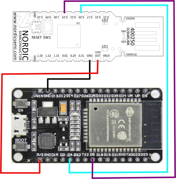
The ESP32 will use pins D4 for RX and D5 for TX, so we need to connect NRF Pin 20 to ESP32 Pin D4 e NRF Pin 24 to ESP32 pin D5. Also notice that this overlay will NOT use hardware flow control since it is not specified on the DTS and neither on our overlay file.

Now we can just compile (your Nordic Connect SDK must be correctly configured…):

west build -p always -b nrf52840dongle_nrf52840 -- -DOVERLAY_CONFIG="overlay-rcp.conf"  -DCONFIG_OPENTHREAD_THREAD_VERSION_1_2=y

And we can flash it now on the dongle. We need to put it on DFU mode by pressing the lateral reset button and waiting for the breathing red led:

# nrfutil-linux pkg generate --hw-version 52 --sd-req=0x00 \
        --application build/zephyr/zephyr.hex \
        --application-version 1 firmware.zip

# nrfutil-linux dfu usb-serial -pkg firmware.zip -p /dev/ttyACM0

Notice that I use nrfutil-linux because the “normal” nrfutil in Arch Linux doesn’t work due to Python versions.

And that’s is, the RCP is done, all that is missing is to connect it to the ESP32, and power it up.

In my test I’m using a standard off the shelf ESP32 development board, and I provide the dongle +3.3v from the ESP32 3.3v pin to the dongle Vout pin (yes, it is Vout.), which means that by powering up the ESP32 through USB I also power up the dongle.

The ESP32 Border Router

All we need now is to flash the ESP32 with the sample border Router. For that we need the latest ESP-IDF SDK to flash the code.

After everything is installed and after running the . ./export.sh script o the esp-idf root directory we can go to examples/openthread/ot_br and compile the Border Router and flash it.

# cd esp-idf/examples/openthread/ot_br
# idf.py build
# idf.py -p /dev/ttyUSB0 flash monitor.

And that’s it, we should have a working Border Router.

Checking it out

After boot we have the following output from the ESP32:

I (0) cpu_start: App cpu up.
I (621) cpu_start: Pro cpu start user code
I (621) cpu_start: cpu freq: 160000000 Hz
I (621) cpu_start: Application information:
I (626) cpu_start: Project name:     esp_ot_br
I (631) cpu_start: App version:      v5.0-dev-2959-g31b7694551-dirty
I (638) cpu_start: Compile time:     May 21 2022 18:09:20
I (644) cpu_start: ELF file SHA256:  404095e613551c1d...
I (650) cpu_start: ESP-IDF:          v5.0-dev-2959-g31b7694551-dirty
I (658) heap_init: Initializing. RAM available for dynamic allocation:
I (665) heap_init: At 3FFAE6E0 len 00001920 (6 KiB): DRAM
I (671) heap_init: At 3FFC0F08 len 0001F0F8 (124 KiB): DRAM
I (677) heap_init: At 3FFE0440 len 00003AE0 (14 KiB): D/IRAM
I (683) heap_init: At 3FFE4350 len 0001BCB0 (111 KiB): D/IRAM
I (690) heap_init: At 40095BC8 len 0000A438 (41 KiB): IRAM
I (697) spi_flash: detected chip: generic
I (701) spi_flash: flash io: dio
I (706) cpu_start: Starting scheduler on PRO CPU.
I (0) cpu_start: Starting scheduler on APP CPU.
I(808) OPENTHREAD:[I] Platform------: RCP reset: RESET_POWER_ON
I(838) OPENTHREAD:[N] Platform------: RCP API Version: 5
I (958) OPENTHREAD: OpenThread attached to netif

Notice that the RCP version is 5, which means we are able to communicate with the RCP throught the UART.

We are set. So we need now to start things up, by connecting to wifi:

> wifi connect -s my_ssid -p my password
...
...
I (127298) esp_netif_handlers: sta ip: 192.168.1.153, mask: 255.255.255.0, gw: 192.168.1.1
I(127798) OPENTHREAD:[N] BorderRouter--: No valid OMR prefix found in settings, generating new one
I(127818) OPENTHREAD:[N] BorderRouter--: Local OMR prefix: fd55:91ab:2b5a:5186::/64 (generated)
I(127818) OPENTHREAD:[N] BorderRouter--: Local on-link prefix: fdad:ed43:b217:0::/64 (generated)

We have now our OMR prefix (Off mesh prefix), on another words the network address that our mesh network will be known from the outside. So we need to bring the network interface up, and start OpenThread:

> ifconfig up
I (279898) OPENTHREAD: Platform UDP bound to port 49153
Done
I (279898) OPENTHREAD: netif up
> thread start
I(284758) OPENTHREAD:[N] Mle-----------: Role disabled -> detached
Done
> I(285448) OPENTHREAD:[N] Mle-----------: Attempt to attach - attempt 1, any-partition 
I(287488) OPENTHREAD:[N] RouterTable---: Allocate router id 44
I(287488) OPENTHREAD:[N] Mle-----------: RLOC16 fffe -> b000
I(287498) OPENTHREAD:[N] Mle-----------: Role detached -> leader
I(287508) OPENTHREAD:[N] Mle-----------: Leader partition id 0x2c603881
I (287518) OPENTHREAD: Platform UDP bound to port 49154
I (290248) OPENTHREAD: Platform UDP bound to port 53535

Now, I already have my Thread network configured, so not sure if we don’t need to first configure it first or a sample network will be generated (in nodes it happens), but anyway, we all set!

Our IPs can be obtain through the ipaddr command and are:

> ipaddr
fdde:ad00:beef:0:0:ff:fe00:fc10
fd55:91ab:2b5a:5186:cf9b:9e83:e87b:b008
fdde:ad00:beef:0:0:ff:fe00:fc00
fdde:ad00:beef:0:0:ff:fe00:b000
fdde:ad00:beef:0:fff5:e276:90b2:62a2
fe80:0:0:0:34c0:14ad:cd5:1e7a
Done
> 

And we can see our OMR prefix based address, which means that if we ran the route -6 command on our Linux machine (or other Linux machines/Windows):

[pcortex@pcortex:coprocessor|main]$ route -6
Kernel IPv6 routing table
Destination                    Next Hop                   Flag Met Ref  Use If
pcortex/128                    [::]                       U    256 1      0 lo
fd04:fdeb:3df3::/64            [::]                       U    100 1      0 enp4s0
fd55:91ab:2b5a:5186::/64       fe80::2662:abff:fedc:b224  UG   100 1      0 enp4s0
fdad:ed43:b217::/64            [::]                       U    100 1      0 enp4s0

We can see that our mesh network: fd55:91ab:2b5a:5186::/64 is on our machine routing table, and this network can be accessed by sending packets to our ESP32 Border Router IPv6 link local address (fe80::2662:abff:fedc:b224) that is assigned to the wifi interface.

So the first stage is done. We can now add nodes, and establish a fully accessible OpenThread Network.

For further testing, the OpenThread site has a series of tutorials, including one regarding SRP (Service registration protocol) that allows Thread nodes to be found through mDNS.

SDRPLAY RSP1A, Arch Linux and udev rules

This is starting to become a recurring topic, but anyway…

Anyway, after a mishap with my udev rules, my RSP1a stopped to be recognized and accessible by Gqrx and other software (such as Sdrangel and sdrpp), mainly with the access denied error, and second on the OS log (using dmesg) the famous Maybe the USB cable is bad? error log message.

Changing the cable with other cables did not solved the issue and I was starting to think the RSP1a might had deliver his last breath. Anyway it would be strange if it was an hardware issue, so it might be the original udev rule that might be wrong…

SUBSYSTEM=="usb",ENV{DEVTYPE}=="usb_device",ATTRS{idVendor}=="1df7",ATTRS{idProduct}=="3000",MODE:="0666"

Specifically for the RSP1a, the vendor ID is 1df7 and the product id is 3000, as it can be seen by running the lsusb command:

...
Bus 003 Device 001: ID 1d6b:0002 Linux Foundation 2.0 root hub
Bus 002 Device 001: ID 1d6b:0003 Linux Foundation 3.0 root hub
Bus 001 Device 002: ID 1df7:3000 SDRplay RSP1a
Bus 001 Device 001: ID 1d6b:0002 Linux Foundation 2.0 root hub
...

So the device is recognized, but programs are unable to access it. Running, as the user root the command udevadm monitor I was seeing the RSP1a connecting and disconnecting continuously in a loop while the system log (dmesg -w) was printing out the “Maybe the USB cable is bad?” while the system tried to associate an USB port/device.

Anyway to keep things short of describing the debugging progress, running the following commands as the user root:

udevadm control --log-priority=debug
journalctl -f

Allows us to see in real time what it was happening, and lo and behold among the messages of connecting and disconnecting loop one was among them:

 mtp-probe: bus: 1, device: 2 was not an MTP device

So changing the original udev rule 66-mirics.rules located on /etc/udev/rules.d to

SUBSYSTEM=="usb",ENV{DEVTYPE}=="usb_device",ATTRS{idVendor}=="1df7", ATTRS{idProduct}=="3000", MODE="666", GROUP="plugdev", ENV{MTP_NO_PROBE}="1"

adding the ENV{MTP_NO_PROBE}=”1″ stopped the loop and, the RSP1a started to work!

Anyway, that was not enough to solve all the problems, since that now, gqrx and other programs required to run as root. This was solved with two changes to the original rule: One to change the format of the MODE parameter and the other to add the USB device to the plugdev system group where my normal user is a member. With this all is working now fine with no issues whatsoever.

Anyway, we will need to reload the new rules after changing them with the following commands:

udevadm control --reload-rules && udevadm trigger

And return back the udev logging level to the standard info level:

udevadm control --log-priority=info

Final thoughts:

Copying udev rules from the internet might be relatively secure, but an important point must be checked: On blogs, just like this, sometimes the ” character does not translate to a real ” double comma character when copying and pasting to a local file. After saving the file with the copied rule one must check if those double comma characters are not an UTF character but a real double comma character. This may also apply to other characters.

od -c 66-mirics.rules 
0000000   S   U   B   S   Y   S   T   E   M   =   =   "   u   s   b   "
0000020   ,   E   N   V   {   D   E   V   T   Y   P   E   }   =   =   "
0000040   u   s   b   _   d   e   v   i   c   e   "   ,   A   T   T   R
0000060   S   {   i   d   V   e   n   d   o   r   }   =   =   "   1   d
0000100   f   7   "   ,       A   T   T   R   S   {   i   d   P   r   o
0000120   d   u   c   t   }   =   =   "   3   0   0   0   "   ,       M
0000140   O   D   E   =   "   6   6   6   "   ,       G   R   O   U   P
0000160   =   "   p   l   u   g   d   e   v   "   ,       E   N   V   {
0000200   M   T   P   _   N   O   _   P   R   O   B   E   }   =   "   1
0000220   "  \n

So before reloading the rules, make sure that the file has no UTF characters, and using a standard editor, like vi, delete and type again the character.

Using in NodeJs raw ECC public keys

A quick post about ECC Public keys that are in their native form of the raw X and Y curve coordinates, and how to use them in NodeJs. Such raw keys are normally outputted by hardware cryptographic devices such as the Microchip ATECC508 or ATECC608. These devices keep the private keys securely, without ever exposing them, and so all cryptographic operations that need to use the private keys need to go through the device.

Any operation that uses a private key for an operation such as signing or encrypting data,  we need the public key to do the other necessary operation, either for verifying if a signature for the data is valid or to decrypt the data. The public key can be obtained from the device at any time and it is a two 32 byte number, for a total of 64 bytes, where 32 bytes is for the X coordinate and the other 32 bytes for the Y coordinate. The device returns the two coordinates concatenated  as X+Y.

So, for the simplest case, we have a signature and a public key in raw ECC format, how do we verify the signature?

Since the Microchip ATECC508 and ATECC608 uses the ECC curve NIST P-256, we need first to instatiate the necessary libraries to handle such cryptographic material:

And at the beginning of our code:

npm i -save crypto elliptic

Notice that we’ve specifically choose the p256 curve for our ec variable, since it is the curve that we are using

var crypto = require("crypto");

var EC = require('elliptic').ec;
var ec = new EC('p256');

An example of a raw public key, already in hex format is:

var pubk = '29C67C7AC65D9C8E78FE82C2D8673DF03BBF0A04D0BD230FE745F5F2BAE7D368F4A4AA73EBFE11838F7189370BC16C256871428EA36952F61006F99178429ADD';

But we can’t use this directly since we need to convert to OpenSSL format. Since the key is not compressed, it has all the components X and Y, this is easily done by prefixing the public key with the 0x04 byte (check 2.2 on RFC5480), and them we can obtain the public key:

var ecpub = '04' + pubk;
var pkec = ec.keyFromPublic(ecpub, 'hex');

The key is now in DER format not compressed. So now, given a message hash and the public key and signature (ecsig) we can check for its validity:

if ( ec.verify( hash, ecsig, pkec ) ) {
    console.log("\nSignature is ok!");
} else {
    console.log("\nSorry, signature is not valid for the provided message hash");
}

JWT Tokens

These crypto devices also have the capability to create JWT tokens, and sign them (again with a private key that is never exposed. These JWT tokens can then be used to provide authentication and identity to any backend service. As the same with the public keys which are provided in raw X and Y coordinates, signatures are provided in raw R and S format. While NodeJS jsonwebtoken library can handle the JWT token, it needs the public key in PEM format, and not in raw X and Y format or DER format.

So we need to convert the raw Public key to PEM format. PEM format is made of a header with specifies some data about the key, namely what curve it belongs to and the raw X and Y key.

There are several ways to do the conversion, but I choose the easiest that is to prefix the raw X and Y values with the necessary header to obtain the key in PEM format.

To obtain the correct header to use we can generate a random ECC NIST P-256 key in PEM format, and extract the header.

openssl ecparam -name prime256v1 -genkey -noout -out tempkey.pem
openssl ec -in tempkey.pem -pubout -outform pem -out temppub.pem

With these two commands we have now a NIST P-256 public key on temppub.pem. We edit the file and remove the header and footer so it looks like this (x.pem file):

MFkwEwYHKoZIzj0CAQYIKoZIzj0DAQcDQgAEkeBXnGHQ00vwtmTRdSDpPvFHJ+Fqv+Ean8bDg0qZf9mufgD9rpg+XfwIeaifGCpDX2LRW+A9hlZP9YeDsLJTbQ==

We can now convert it to hex and obtain the header by removing the last 65 bytes ( 0x04 + 64 key bytes):

base64 -d x.pem | xxd -i
  0x30, 0x59, 0x30, 0x13, 0x06, 0x07, 0x2a, 0x86, 0x48, 0xce, 0x3d, 0x02,
  0x01, 0x06, 0x08, 0x2a, 0x86, 0x48, 0xce, 0x3d, 0x03, 0x01, 0x07, 0x03,
  0x42, 0x00, 0x04, 0x91, 0xe0, 0x57, 0x9c, 0x61, 0xd0, 0xd3, 0x4b, 0xf0,
  0xb6, 0x64, 0xd1, 0x75, 0x20, 0xe9, 0x3e, 0xf1, 0x47, 0x27, 0xe1, 0x6a,
  0xbf, 0xe1, 0x1a, 0x9f, 0xc6, 0xc3, 0x83, 0x4a, 0x99, 0x7f, 0xd9, 0xae,
  0x7e, 0x00, 0xfd, 0xae, 0x98, 0x3e, 0x5d, 0xfc, 0x08, 0x79, 0xa8, 0x9f,
  0x18, 0x2a, 0x43, 0x5f, 0x62, 0xd1, 0x5b, 0xe0, 0x3d, 0x86, 0x56, 0x4f,
  0xf5, 0x87, 0x83, 0xb0, 0xb2, 0x53, 0x6d

Now in NodeJs:

var pubk_header = ‘3059301306072a8648ce3d020106082a8648ce3d030107034200’;
var key = Buffer.from( pubk_header + ’04’ + pubk, ‘hex’);

var pub_pem = “—–BEGIN PUBLIC KEY—–\n” + key.toString(‘base64’) + “\n—–END PUBLIC KEY—–“;

jwt.verify( jwttoken, pub_pem , function(err, decoded) {
   if (err) {
     console.log(‘Failed to verify token.’ );
     console.log(err);
   } else {
       console.log(“Token is valid!”);
       console.log(“Decoded token:”, decoded);
   }
 });

And that’s it. A bit of hackish, but it works fine. If using other curves other than NIST P-256, the appropriate curve and header must be used so that the validations work as expected.

Zephyr RTOS – Initial setup and some tests with Platformio and the NRF52840 PCA10059 dongle

This posts shows a quick how to for installing and configuring the Zephyr RTOS project on Arch Linux. In reality this post is a mashup of already a set of instructions and tutorials from the Zephyr project home page and also Adafruits Zephyr instructions:

  1. Zephyr RTOS Generic install instructions: https://docs.zephyrproject.org/latest/getting_started/index.html
  2. Adafruits install instructions with setting up Pythons virtual environments: https://learn.adafruit.com/blinking-led-with-zephyr-rtos/installing-zephyr-linux
  3. Specific instructions from the Zephyr RTOS project documentation for Arch Linux: https://docs.zephyrproject.org/latest/getting_started/installation_linux.html

By mashing up all the collected instructions from the above link, here it is my instructions:

Install some needed packages for Arch Linux:

sudo pacman -S git cmake ninja gperf ccache dfu-util dtc wget python-pip python-setuptools python-wheel tk xz file make

Check Python:
Note that Python2 is discontinued, and so all Python programs and packages are for Python 3 version.

One thing that I also had messed up was that the default Python environment on one of my machines was using Platformio penv directory, instead of the Python3 global environment. Make sure that we are using the global environment and not other non global environment.

A (better) approach as described on the Adafruit tutorial is to use Python virtual environments and so we need to install virtual environment support:

sudo pip3 install virtualenv virtualenvwrapper

and we need to change the .bashrc file at our home directory to add virtual environment support:

# For using Python and Venvs
export PATH=~/.local/bin:$PATH
export WORKON_HOME=$HOME/.virtualenvs
export VIRTUALENVWRAPPER_PYTHON=/usr/bin/python3
source /usr/bin/virtualenvwrapper.sh

Execute now source ~/.bashrc to load the new configuration

Since we will load our firmware on the NRF52840 dongle through DFU we also install the nrfutil:

pip install nrfutil

Installing Zephyr RTOS:
I’ll be installing the Zephyr RTOS files and SDK on /opt/Develop:

mkvirtualenv zephyr

mkdir /opt/Develop
cd /opt/Develop
mkdir zephyrproject

workon zephyr
pip install west nrfutil
west init ./zephyrproject

cd zephyrproject
west update

we also installed the nrfutil utility on this virtual environment.

To end the Zephyr RTOS setup we install the also the latest requirements:

pip install -r zephyr/scripts/requirements.txt

and that’s it.

Installing the SDK:
We can install the SDK on some of the predefined directories or our own directories, just make sure that in the later case some environmental variables are set to allow the Zephyr RTOS find the SDK:

wget https://github.com/zephyrproject-rtos/sdk-ng/releases/download/v0.11.3/zephyr-sdk-0.11.3-setup.run

(zephyr) [pcortex@pcortex:Develop]$ ./zephyr-sdk-0.11.3-setup.run
Verifying archive integrity... All good.
Uncompressing SDK for Zephyr  100%  
Enter target directory for SDK (default: /home/pcortex/zephyr-sdk/): /opt/Develop/zephyr-sdk-0.11.3

It is recommended to install Zephyr SDK at one of the following locations for automatic discoverability in CMake:
  /opt/zephyr-sdk-0.11.3

Note: The version number '-0.11.3' can be omitted.

Do you want to continue installing to /opt/Develop/zephyr-sdk-0.11.3 (y/n)?
y
md5sum is /usr/bin/md5sum
Do you want to register the Zephyr-sdk at location: /opt/Develop/zephyr-sdk-0.11.3
  in the CMake package registry (y/n)?
y
/opt/Develop/zephyr-sdk-0.11.3 registered in /home/pcortex/.cmake/packages/Zephyr-sdk/847bb3ddf638ff02dce20cf8dc171b02
Installing SDK to /opt/Develop/zephyr-sdk-0.11.3
Creating directory /opt/Develop/zephyr-sdk-0.11.3
Success
 [*] Installing arm tools...
 [*] Installing arm64 tools...
 [*] Installing arc tools...
 [*] Installing nios2 tools...
 [*] Installing riscv64 tools...
 [*] Installing sparc tools...
 [*] Installing x86_64 tools...
 [*] Installing xtensa_sample_controller tools...
 [*] Installing xtensa_intel_apl_adsp tools...
 [*] Installing xtensa_intel_s1000 tools...
 [*] Installing xtensa_intel_bdw_adsp tools...
 [*] Installing xtensa_intel_byt_adsp tools...
 [*] Installing xtensa_nxp_imx_adsp tools...
 [*] Installing xtensa_nxp_imx8m_adsp tools...
 [*] Installing CMake files...
 [*] Installing additional host tools...
Success installing SDK.

You need to setup the following environment variables to use the toolchain:

     export ZEPHYR_TOOLCHAIN_VARIANT=zephyr
     export ZEPHYR_SDK_INSTALL_DIR=/opt/Develop/zephyr-sdk-0.11.3

Update/Create /home/pcortex/.zephyrrc with environment variables setup for you (y/n)?
y
SDK is ready to be used.

and the new .bashrc configuration is now:

# For using Python and Venvs
export PATH=~/.local/bin:$PATH
export WORKON_HOME=$HOME/.virtualenvs
export VIRTUALENVWRAPPER_PYTHON=/usr/bin/python3
source /usr/bin/virtualenvwrapper.sh

export ZEPHYR_TOOLCHAIN_VARIANT=zephyr
export ZEPHYR_SDK_INSTALL_DIR=/opt/Develop/zephyr-sdk-0.11.3

If we do not add the lines to the .bashrc file when starting up a project or working on it, we need to execute the zephyr-env.sh script on the Zephyr Rtos project directory.

Flashing the Blink sample program on the NRF52840 dongle:

This is pretty much documented on the NRF52840 Dongle page at NRF52840 Dongle documentation.

In our case is just something like:

cd /opt/Develop/zephyrproject
echo Select the PEnv zephyr
workon zephyr
west build -b nrf52840dongle_nrf52840 zephyr/samples/basic/blinky
nrfutil pkg generate --hw-version 52 --sd-req=0x00 --application build/zephyr/zephyr.hex --application-version 1 blinky.zip

and now we need to plugin and enable the dongle dfu mode to flash the firmware:

nrfutil dfu usb-serial -pkg blinky.zip -p /dev/ttyACM0

and the green led on the board should start to blink.

Using Platformio:
While the NRF52840 development kit from Nordic is supported (PCA10056) in both Zephyr and Platformio, the dongle version (PCA10059) is only supported on Zephyr. Since DFU upload is not supported for these boards, so we need some trickery to be able to do it from the Platformio Upload command.

To use to Platformio to target the dongle board, a project targeting the NRF52840_DK board and the Zephyr framework is created and then modifying the platformio.ini we can also target the dongle. For uploading the firmware a custom upload script is used that uses nrfutil to create a non signed DFU package and upload it.

[env:nrf52840_dongle]
platform = nordicnrf52
board = nrf52840_dk
framework = zephyr
board_build.zephyr.variant = nrf52840dongle_nrf52840
extra_scripts = dfu_upload.py
upload_protocol = custom


[env:nrf52840_dk]
platform = nordicnrf52
board = nrf52840_dk
framework = zephyr

For the NRF52840 dongle we pass to the Platformio build system the board variant used by Zephyr that targets the dongle, which is the nrf52840dongle_nrf52840 (where it was previously nrf52840_pca10059). Since the dongle hasn’t an on board debugger for uploading firmware through JTAG/Stlink, we need to use a custom upload method with an associated python script:

import sys
import os
from os.path import basename
Import("env")

platform = env.PioPlatform()

def dfu_upload(source, target, env):
    firmware_path = str(source[0])
    firmware_name = basename(firmware_path)

    genpkg = "".join(["nrfutil pkg generate --hw-version 52 --sd-req=0x00 --application ", firmware_path, " --application-version 1 firmware.zip"])
    dfupkg = "nrfutil dfu usb-serial -pkg firmware.zip -p /dev/ttyACM0"
    print( genpkg )
    os.system( genpkg )
    os.system( dfupkg )

    print("Uploading done.")


# Custom upload command and program name
env.Replace(PROGNAME="firmware", UPLOADCMD=dfu_upload)

This dfu_upload.py file is put side by side with the platformio.ini file and has some hardcoded values, such as the upload port, but it gets the job done.

GQRX and SDRPlay RSP1A

I’ve own a SDRPlay RSP1A SDR and since I use Linux I’ve never used SDRUno, just CubicSDR that works fine with the RSP1A.

Nevertheless one thing that annoys me on CubicSdr is that we can only pipe audio out from the application, while on GQRX we can pipe data out through UDP, and hence we can pipe it out to basically anywhere and not be dependent of the audio interface and audio routing on the local PC.

But the truth is that I never was able to make GQRX to work with SDRPlay. I’ve followed some tutorials around the net such as this: http://thomasns.io/gqrx.html and this http://dk3ml.de/2019/01/12/running-sdrplay-with-gqrx-on-ubuntu-18-10/ but at the end I always had this, even with the latest versions of GQRX that support SDRPlay:

GQRX SDRPlay

While I can hear the FM station at the above frequency the frequency panadapter has a hump at the middle and that’s it, not exactly what I was expecting.

Well the issue is that GQRX at startup does not setup SDRPlay RSP1A propertly and so it shows the above behavior.

So if we get the initial GQRX settings for the SDRPlay:

SDRPlay Settings

it looks fine, but as we’ve seen the end result is not as expected. So what we need to do is to re-enter the settings again in a certain order to make this work:

  1. Stop the data capture, without exiting GQRX (press the Play button)
  2. Edit the Device settings and choose any other than SDRPlay, and then choose again SDRPlay again. Make sure Bandwidth is set to 0.6Mhz.
  3. DEfault SDRPlay Settings

  4. As we can see the default Input rate is set to 2MBps.
  5. Press Apply, and if we start the capture it should work now, but we have a RSP1A,so…
  6. Open up again the settings and change the Input Rate to the maximum that RSP1A supports: 10MBps

The end result is this:

Proper SDRPlay on GQRX

And now it works as it should.

Conclusion:
While a bit annoying it’s good to see GQRX working fine with SDRPlay RSP1A. Still through GQRX we can’t control the FM and DAB notch filters, which CubicSDR can.

MQTT-SN Paho gateway and UDP6

Sometimes simple things can take a lot of time, such as this: How to make the Paho MQTT-SN gateway to listen to UDP6 instead of the standard UDP4 ports…

Introduction:
A lot can be written about MQTT-SN and it’s counterpart MQTT. To keep it simple and short, MQTT-SN (SN for Sensor Networks) uses UDP instead of TCP/IP and is streamlined to be more efficient in transmitting information, and so more adequate to be used on constrained devices than MQTT on WSN (Wireless Sensor Networks).
One important key element in using MQTT-SN is that MQTT-SN clients use UDP broadcasts to find gateways, and so they have no need to hardcode a broker address on the firmware code, since gateways can be dynamically discover at run time. Still MQTT-SN depends on MQTT broker to connect to the outside world (and that’s why MQTT-SN is a gateway, not a broker), but that is configured at the gateway level, not at the node level.

Compiling and configuring:
If we just clone the MQTT-SN Github repository, we can for UDP version 4, just do the following:

git clone https://github.com/eclipse/paho.mqtt-sn.embedded-c
cd MQTTSNGateway/
make 

And that’s it. On the Build/ directory there are the executables, among them the MQTT-SNGateway, and on the current directory there is the configuration file gateway.conf that is used by the gateway to startup. Out of the box the only thing that we need to change is the upstream MQTT broker address that by default points to the iot.eclipse.org MQTT broker, the gateway name, and maybe the ports:

BrokerName=iot.eclipse.org
BrokerPortNo=1883
BrokerSecurePortNo=8883

GatewayID=1
GatewayName=PahoGateway-01
KeepAlive=900

# UDP
GatewayPortNo=10000
MulticastIP=225.1.1.1
MulticastPortNo=1883

So if we start with this config, the output is:

20190612 142837.189 PahoGateway-01 has been started.

 ConfigFile: ./gateway.conf
 PreDefFile: ./predefinedTopic.conf
 SensorN/W:  UDP Multicast 225.1.1.1:1883 Gateway Port 10000
 Broker:     172.17.0.4 : 1883, 8883
 RootCApath: (null)
 RootCAfile: (null)
 CertKey:    (null)
 PrivateKey: (null)

We can see that in this case my upstream broker is at 172.17.0.4 (a docker image of the Mosquitto broker).

Checking which ports the gateway is listening:

root@b74f5ad3fd8e:/app/mqttsn# lsof -c MQTT-SNGateway -a -i4
COMMAND   PID USER   FD   TYPE  DEVICE SIZE/OFF NODE NAME
MQTT-SNGa 923 root    3u  IPv4 5017719      0t0  UDP *:10000 
MQTT-SNGa 923 root    4u  IPv4 5017720      0t0  UDP *:1883 
root@b74f5ad3fd8e:/app/mqttsn# lsof -c MQTT-SNGateway -a -i6
root@b74f5ad3fd8e:/app/mqttsn# 

We can see that the gateway is listening on UDP4 and not on UDP6.

Supporting UDP6:
Sensor networks such as Openthread networks work only with IPv6… and so the MQTT-SN gateway must listen to UDP6 instead of UDP4. It can still communicate with the MQTT broker over IPv4, and hence bridging the IPv4 network with the IPv6 sensor network.

To add support to UDP6 for the MQTT-SN gateway we need to change the Makefile (and hence the time to find information for this little bit… ) to change the protocol used by the sensor network and recompile.

So again on the source folder for the MQTT-SN gateway, edit the Makefile and change the following line from

SENSORNET := udp

to

SENSORNET := udp6

Or just change the parameter at the make call: make SENSORNET=udp6

And then clean and build:

make clean
make SENSORNET=udp6

We have now a MQTT-SN gateway version for UDP6. We need now to add the configuration entries to the gateway configuration file so that the UDP6 configuration is set:

#UDP v6
GatewayUDP6Broadcast = ff03::1
GatewayUDP6Port = 47193
GatewayUDP6If = wpan0

We can now start the UDP6 MQTT-SN enabled version:

20190612 144124.280 PahoGateway-01 has been started.

 ConfigFile: ./gateway.conf
 PreDefFile: ./predefinedTopic.conf
 SensorN/W:   Gateway Port: 47193 Broadcast Address: ff03::1 Interface: wpan0
 Broker:     172.17.0.4 : 1883, 8883
 RootCApath: (null)
 RootCAfile: (null)
 CertKey:    (null)
 PrivateKey: (null)

Specifically in this case the GatewayUDP6If interface that is defined is the NCP OpenThread interface, but it should be the interface where we want the gateway to listen. The broadcast address is the address defined on the Nordic SDK for Thread, namely on the file mqttsn_packet_internal.h.

Checking the ports:

root@b74f5ad3fd8e:/app/mqttsn# lsof -c MQTT-SNGateway -a -i4
root@b74f5ad3fd8e:/app/mqttsn# lsof -c MQTT-SNGateway -a -i6
COMMAND   PID USER   FD   TYPE  DEVICE SIZE/OFF NODE NAME
MQTT-SNGa 947 root    4u  IPv6 5050130      0t0  UDP *:47193 
root@b74f5ad3fd8e:/app/mqttsn# 

And that’s it.

Conclusion:
A simple lack of documentation regarding MQTT-SN and UDP6 took a while to solve since it was so “simple”.

Still one still needs two compiled versions of MQTT-SN for supporting UDP4 and UDP6 based networks, but since MQTT-SN is light there is no big issue with this.

Docker container web interface – Portainer and Riot-OS Development

This post is a follow up of starting up with RIOT-OS. To be able to develop with RIOT-OS an easy (and easier) way to do so is just to install docker and web UI docker interface Portainer to control docker.

So we will install Docker, Portainer, and finally the RIOT-OS building environment.

Installing Docker and Portainer, is an initial stepping stone for using the dockerized development environment for RIOT-OS, since I don’t want to install all the development environments in my machine.

Installing Docker:
On Arch-Linux is as simple as installing the Docker package using pacman, enabling the services and rebooting.
Basically we need to run, as root the following commands:

pacman -S docker
systemctl enable docker.service
reboot

After rebooting the following command should return some information

docker info

A sample output is:

Containers: 2
 Running: 0
 Paused: 0
 Stopped: 2
Images: 9
Server Version: 18.09.0-ce
Storage Driver: overlay2
 Backing Filesystem: extfs
 Supports d_type: true
 Native Overlay Diff: false
Logging Driver: json-file
Cgroup Driver: cgroupfs
Plugins:
 Volume: local
 Network: bridge host macvlan null overlay
 Log: awslogs fluentd gcplogs gelf journald json-file local logentries splunk syslog
...
...
...

Installing Portainer
Installing the Docker Portainer Web UI is as simple as:

docker pull portainer/portainer

To run Portainer a set of complete instructions on this page, but basically on the simplest way is:

$ docker volume create portainer_data
$ docker run -d -p 9000:9000 --name portainer --restart always -v /var/run/docker.sock:/var/run/docker.sock -v portainer_data:/data portainer/portainer

We can now check if the docker image is up:

$ docker ps
CONTAINER ID        IMAGE                 COMMAND             CREATED             STATUS              PORTS                    NAMES
7a38ae7fc922        portainer/portainer   "/portainer"        4 seconds ago       Up 3 seconds        0.0.0.0:9000->9000/tcp   portainer

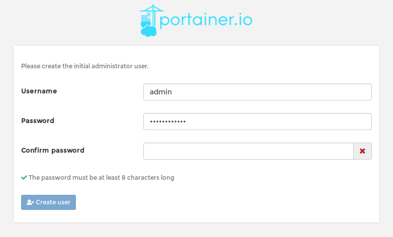
Since I have already ran the Portainer container, the initial setting up steps when accessing the URL HTTP://localhost:9000 do not appear, but we need to choose:

  1. A set of credentials to use as de administrator for portainer
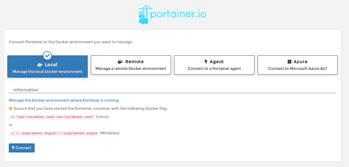
  2. The local machine registry to connect to the local docker containers.

1- At initial access we define an user and password:

Portainer Credentials

2- Then we connect to our local docker instance:
Portainer Local Docker

Press Connect and then we can now access our Docker instance from Portainer:
Portainer Main Screen

Pressing the Local Docker Connection we can now manage our docker resources.

Installing the build environment for RIOT-OS
We can do it by two ways:

From the command line:

docker pull riot/riotbuild

or use Portainer:

This container is very big, so we need to wait some time for the container image download. The command line shows in greater detail the download process.

After the image is downloaded, we can follow these instructions for building our apps using the docker container as the build environment.

After the image is installed:

To use is is as simple as going the the examples directory and do:

make BUILD_IN_DOCKER=1

From this we are now able to build based RIOT-OS applications for several targets, including the ESP8266/ESP32.

As we can see we even don’t need to have a running container, just the image.

Arch Linux with full encrypted disks

So, I’ve bought a new light weight laptop, an HP Envy 13.3 1.2Kg I7, where I wiped out Windows 10 and installed Arch Linux.

Just for security reasons I’ve decided to do a full disk encryption install, including boot.

There are several instructions on the Web, including videos on youtube in how to do it, and so on this gist I have my instructions for the installation, based off course in other gists and instructions.

In this post is the configuration instructions that worked for me and also to allow better find from google/bing/ddg.

# WARNING: WORK IN PROGRESS, USE THESE STEPS WITH CAUTION. IT WILL CLEAR ALL DISK DATA!!
I REALLY recommend first to use a Virtual Box machine with EFI support enabled to test everything before doing it on a real machine.

# Arch installation on a HP ENVY 13 inch laptop (ah0006np part number: 16GB Ram, 512GB SSD)

OBJECTIVE:
Install Arch Linux with encrypted boot, root and swap filesystems and boot from UEFI, completly dumping Windows on the process.
No dual boot.
Windows, if necessary will be run on a Virtual Machine and re-use the Windows key that came with the laptop.

The configuration will be LVM on LUKS. Also a major difference from other tutorials is that the boot partition is also encrypted, and not a standard partition.

# Results so far:

– Disk encryption ok. GRUB boots slow (20s). Otherwise works fine.
– Wireless works OOTB, but errors on dmesg output from time to time when there is high network traffic.
– Sound and microfone works ok.
– Webcam does work but needs configuration: See below at the end.
– Keyboard special keys work fine (brightness, Sound, Mute), including keyboard background lights, but F6 sound Mute Led does not work.
– Some screen corruption with the Intel Driver either SNA or UXA. Nouveau crashes, nvidia driver didn’t work. To be checked -> Issue with QT 5 and Konsole/Kate applications, not a Intel Driver issue.
– KDE SDDM doesn’t recover well if screen DPMS is activated. I’ve disable it so far to solve it.
– Suspend/resume works fine.
– Battery time so far, around 4/5 hours.


# Desired disk layout:

+---------------+----------------+----------------+----------------+
|ESP partition: |Boot partition: |Volume 1:       |Volume 2:       |
|               |                |                |                |
|/boot/efi       |/boot           |root            |swap            |
|               |                |                |                |
|               |                |/dev/vg0/root   |/dev/vg0/swap   |
|/dev/sda1      |/dev/sda2       +----------------+----------------+
|unencrypted    |LUKS encrypted  |/dev/sda3 encrypted LVM on LUKS  |
+---------------+----------------+---------------------------------+

The final result is to have an Arch Linux Installation with full disk encryption and with a basic set of applications such as the KDE Plasma Desktop.

These instructions have several sources, namely:
https://grez911.github.io/cryptoarch.html
and this WordPress post.

The installation process on this guide is for the Arch Linux installation onto an HP Envy 13, 16GB RAM with 512MB ssd laptop. This laptop comes with Windows 10 Home installed, and as far as my model goes, it comes with an Intel WiFi board and a WD Sandisk SN520 512GB NVME SSD.

The official Arch installation guide contains more details that you should refer to during this installation process.
That guide resides at: https://wiki.archlinux.org/index.php/Installation_Guide

## Boot from image

Download the archlinux-\*.iso image from https://www.archlinux.org/download/ and its GnuPG signature.
Use gpg –verify to ensure your archlinux-\*.iso is exactly what the Arch developers intended. For example
at the time of installation:

$ gpg --verify archlinux-2017.10.01-x86_64.iso.sig
gpg: Signature made Sun 01 Oct 2017 07:29:43 AM CEST using RSA key ID 9741E8AC
gpg: Good signature from "Pierre Schmitz "
gpg: WARNING: This key is not certified with a trusted signature!
gpg:          There is no indication that the signature belongs to the owner.
Primary key fingerprint: 4AA4 767B BC9C 4B1D 18AE  28B7 7F2D 434B 9741 E8AC

Currently the Arch ISO is archlinux-2018.11.01-x86_64.iso.

Burn the archlinux-\*.iso to a 1+ Gb USB stick. You can use the dd command, unetbootin or Etcher.

Connect the USB stick to the usb port and power on/cycle the machine to boot.
If your USB stick fails to boot, ensure that Secure Boot is disabled in your UEFI configuration.

Note: To access the BIOS on the Envy Laptop, turn on the laptop and press several times the ESC key or the F10 key to access the BIOS while the screen is black.
First I moved the boot order to have the USB boot at the top.
Then we need to disable the secure boot option and press F10 to save. Confirm saving it.

Attention now: There is a confirmation screen to really commit the secure boot option change. Enter the requested code and save.

After booting up:

Set your keymap only if not you are not using the default English keyboard.

$ loadkeys pt-latin1

We can now, if required backup the HP recovery partition, that I suppose is the Windows Install Media.

# Connect to the Internet.

Execute the wifi-menu command and select a Wifi network. On this HP Envy, the wireless card (Intel) was detected with no issues.

Check with the “ip a” command if there is network connection.

## Prepare your hard disk

In the next steps we will create necessary partitions and encrypt the main partition.

Find the correct block device

$ lsblk

In my case the correct block device (the NVME SSD of my laptop) is ‘nvme0n1’. (Depends on the machine)

Create and size partitions appropriate to your goals using gdisk.

$ gdisk /dev/nvme0n1

Press p to show the partitions.

In my case I have a 260Mb EFI partition, a 16MB Reserved Microsoft Partition, a 460GB partition and a 980MB and another 15GB partition.

From this point on, everything that is to be done, will destroy the disk data.

# Delete all partitions on disk

Use the d command to delete all partitions. Use d, then partition number. Repeat for all partitions

Press o to create the GPT.

Create three partitions: One for the EFI, one for boot and the other will be used to have the Arch Linux installation. To create a partition, press n:

1. Partition 1 = 512 MB EFI partition (Hex code EF00). Initial Sector: ; End: 512M; Type: EF00
2. Partition 2 = 1GB Boot partition (Hex code 8300)
3. Partition 3 = Size it to the last sector of your drive. (default) (Hex code 8E00 – Linux LVM Partition)

Review your partitions with the ‘p’ command.
Write your gdisk changes with ‘w’.

Check again the names with the blkid command to know the partitions name:

1. EFI: /dev/nvme0n1p1
2. BOOT: /dev/nvme0n1p2
3. Arch: /dev/nvme0n1p3

# Create filesystems
The EFI filesystem must be FAT32:

$ mkfs.vfat -F 32 /dev/nvme0n1p1

The other filesystems are to be encrypted.

(optional) Before creating the partitions we can use the command

cryptsetup benchmark 

to see how fast the different encryption algoritms are.

# Encrypted /boot partition

$ cryptsetup -c aes-xts-plain64 -h sha512 -s 512 --use-random luksFormat /dev/nvme0n1p2
$ cryptsetup open /dev/nvme0n1p2 cryptboot
$ mkfs.ext4 /dev/mapper/cryptboot

The first command will ask for the disk passphrase. Do not forget it!.

ATTENTION:
The first crypsetup command will set the LUKS with default iter-time parameters, which may or may not make grub to boot slow (around 20s). If this is not fine add the following parameter: –iter-time=5000 (This will affect security, so use a large key phrase)

The last command will create a /dev/mapper/cryptboot device.
We can check that it was created with the command ls /dev/mapper

# Create encrypted LUKS device for the LVM

cryptsetup -c aes-xts-plain64 -h sha512 -s 512 --use-random luksFormat /dev/nvme0n1p3
cryptsetup open /dev/nvme0n1p3 cryptlvm

## Create encrypted LVM partitions

These steps will create the required root partition and an optional partition for swap.
Modify this structure only if you need additional, separate partitions. The sizes used below are only suggestions.
The VG and LV labels ‘ArchVG, root and swap’ can be changed to anything memorable to you. Use your labels consistently, below!

$ pvcreate /dev/mapper/cryptlvm
$ vgcreate ArchVG /dev/mapper/cryptlvm
$ lvcreate -L +16G ArchVG -n swap
$ lvcreate -l +100%FREE ArchVG -n root

Again, we can see on /dev/mapper if the logical volumes where created.

## Create filesystems on your encrypted partitions

$ mkswap /dev/mapper/ArchVG-swap
$ mkfs.ext4 /dev/mapper/cryptboot
$ mkfs.ext4 /dev/mapper/ArchVG-root

Mount the new system

mount /dev/mapper/ArchVG-root /mnt
swapon /dev/mapper/ArchVG-swap
mkdir /mnt/boot
mount /dev/mapper/cryptboot /mnt/boot
mkdir /mnt/boot/efi
mount /dev/nvme0n1p1 /mnt/boot/efi

# Install the Arch system:

This installation command provides a decent set of basic system programs which will also support WiFi when initially booting into your Arch system.

At this point we need to have a network connection. Since the HP only has Wifi connection, we need to setup the WiFi connection. Other alternative is to use an Ethernet USB dongle that is recognized by the Arch boot ISO.
Also, if you are behind a proxy, you can set the http_proxy and https_proxy variables to access the internet.

(Optional) Use reflector to speedup download (credit goes to u/momasf)

Change COUNTRY to (surprise) your country name.

pacman -Sy reflector
reflector --country 'COUNTRY' --age 12 --protocol https --sort rate --save /etc/pacman.d/mirrorlist

I won’t install base-dev here to save time at the installation.

$ pacstrap /mnt base grub-efi-x86_64 efibootmgr dialog wpa_supplicant vim

# Create and review FSTAB
The -U option pulls in all the correct UUIDs for your mounted filesystems.

 $ genfstab -U /mnt >> /mnt/etc/fstab
 $ nano /mnt/etc/fstab  # Check your fstab carefully, and modify it, if required.
 

Enter the newly installed system

$ arch-chroot /mnt /bin/bash

Set the system clock, you can replace UTC with your actual timezone

$ ln -fs /usr/share/zoneinfo/Europe/Lisbon /etc/localtime
$ hwclock --systohc --utc

Assign your hostname

$ echo mylaptop > /etc/hostname

My requirements for the locale are:
– Metric system
– 24h time format
– dd/mm/yyyy date format
– Portuguese language
– A4 paper size
– But all help, error messages are in English

The *pt_PT.UTF-8* plus *en_US.UTF-8* locale meets those requirements. To set up this locale:

– In /etc/locale.gen

en_US.UTF-8 UTF-8
pt_PT.UTF-8 UTF-8

– In /etc/locale.conf, you should **only** have this line:

LANG=en_US.UTF-8

We will change other settings on Bash profile.

Now run:

$ locale-gen

Create a new file vconsole.conf so that the console keymap is correctly set at boot. Create the file and add the following line:

KEYMAP=pt-latin1

Set your root password

$ passwd

Create a User, assign appropriate Group membership, and set a User password.

$ useradd -m -G audio,games,log,lp,optical,power,scanner,storage,video,wheel -s /bin/bash memyselfandi
$ passwd memyselfandi

Configure mkinitcpio with the correct HOOKS required for your initrd image

$ nano /etc/mkinitcpio.conf

Use this HOOKS statement: (I’ve moved keyboard before keymap, encrypt and so on…)

HOOKS="base udev autodetect modconf block keyboard keymap encrypt lvm2 resume filesystems fsck"

Generate your initrd image

mkinitcpio -p linux

## Install and configure Grub-EFI
Since we have the boot partition INSIDE the encrypted disk, we need to add the following option to the Grub options:

Edit the file /etc/default/grub and uncomment the following line:

GRUB_ENABLE_CRYPTODISK=y

And then we can install Grub, which will create an EFI entry named ArchLinux

grub-install --target=x86_64-efi --efi-directory=/boot/efi --bootloader-id=ArchLinux

Edit /etc/default/grub so it includes a statement like this:

GRUB_CMDLINE_LINUX="cryptdevice=/dev/nvme0n1p3:cryptlvm resume=/dev/mapper/ArchVG-swap i915.enable_guc=3"

I’ve also added the i915 configuration line.

Other way of doing it is to use UUID:

blkid /dev/nvme0n1p3 -s UUID -o value

And use the UUID outputed on this command line:

GRUB_CMDLINE_LINUX="cryptdevice=UUID=55994-XXXX-xXXXX-XXXXX:cryptlvm resume=/dev/mapper/ArchVG-swap"

Generate Your Final Grub Configuration:

$ grub-mkconfig -o /boot/grub/grub.cfg

At this point there are some errors regarding failing to connect to lvmetad, which are normal and can be ignored.

# Mounting /boot without password request
Grub will ask for passwords to access the encrypted volumes. We can do this automatically:

dd bs=512 count=8 if=/dev/urandom of=/etc/key
chmod 400 /etc/key
cryptsetup luksAddKey /dev/nvme0n1p2 /etc/key
echo "cryptboot /dev/nvme0n1p2 /etc/key luks" >> /etc/crypttab

# Mounting root LVM without password prompt

dd bs=512 count=8 if=/dev/urandom of=/crypto_keyfile.bin
chmod 000 /crypto_keyfile.bin
cryptsetup luksAddKey /dev/nvme0n1p3 /crypto_keyfile.bin
sed -i 's\^FILES=.*\FILES="/crypto_keyfile.bin"\g' /etc/mkinitcpio.conf
mkinitcpio -p linux
chmod 600 /boot/initramfs-linux*

The mkinitcpio.conf FILES line will look like:

FILES="/crypto_keyfile.bin"

# Enable Intel microcode CPU updates (if you use Intel processor, of course)

pacman -S intel-ucode
grub-mkconfig -o /boot/grub/grub.cfg

# Check EFI Boot Manager
Check that the EFI Boot manager has the ArchLinux entry:

$ efibootmgr

For example if ArchLinux entry is Boot0003, check if on the boot order, 0003 is on the head of the list.
If not change the order with:

$ efibootmg -o 0003,0002,0001,0000

Exit Your New Arch System

$ exit

Unmount all partitions

$ umount -R /mnt
$ swapoff -a

Reboot and Enjoy Your Encrypted Arch Linux System!

reboot

___

# Setup system

We need again to connect to the internet, so run again the *wifi-menu*.

Install bash completion for reduced typing effort and other packages if necessary:

$ pacman -S sudo bash-completion base-devel git

To be able to use sudo from your normal user add wheel to sudoers.

$ EDITOR=nano visudo

Uncomment the line

%wheel      ALL=(ALL) ALL

From this point on, it really depends of what need there is for the machine.

# Making the webcam to work.
The webcam id appears at the lsusb output:

Bus 002 Device 001: ID 1d6b:0003 Linux Foundation 3.0 root hub
Bus 001 Device 003: ID 8087:0a2a Intel Corp. 
Bus 001 Device 002: ID 04ca:7090 Lite-On Technology Corp. 
Bus 001 Device 001: ID 1d6b:0002 Linux Foundation 2.0 root hub

The webcam is the Bus 001:002 device: ID 04ca:7090.
Add the following rule at /etc/udev/rules.d

KERNEL=="video[0-9]*", SUBSYSTEM=="video4linux", SUBSYSTEMS=="usb", ATTRS{idVendor}=="04ca", ATTRS{idProduct}=="7090", SYMLINK+="video-cam"

Load the module to activate the webcam:

modprobe uvcvideo

The /dev/video0 and 1 devices should appear.

MakeBlock STEM mbot Robot – Using nodeJS to control mbot through BLE

A few weeks ago I’ve bought a mbot robot out of curiosity (also as a gift), since they became available at a nearby major electronic retailer and cheaper than buying them online.

The mbot is a robot chassis with two wheels, some external and onboard sensors, including an external ultrasonic sensor, and all this supported on a custom version of Arduino 328 board whish incorporates a motor driver, battery charger and so on. The version that I’ve bought also came with a LED Matrix display where it is possible to draw faces, text and numbers (mbot Face version).

The mbot robot can be controlled or used by either some Android (and IOS) mobile applications, or by using the Scratch programming environment. MakeBlock has a specific mbot version for Scratch called mblock that supports a set of new programming blocks to control the robot. The use of Scratch and mbot makes it ideal combination for teaching kids about programming and robotics.

We caan communicate/interface with mbot either by using an USB cable, or either by Low Power Bluetooth (the mbot BLE version) or through a 2.4GHz radio (the mbot 2.4GHz version). The 2.4Ghz version is more adequate for a classroom environment, since each robot is automatically bounded by radio to the 2.4GHz USB computer stick radio controller, which basically makes it plug and go and no need to fiddle with BLE discovery and bounding.

Anyway, the version that I have is the BLE one, and this post is about how to use NodeJS with the BLE Noble Library to communicate with mbot when using the factory firmware.

Requisites:

To make this work we need to have some requisites first:

Since mbot uses BLE, the computer must support also BLE. In my case I’m using the CSR 4 BLE dongle available on eBay, Ali and so on, to have BLE support on my computer.

The mbot must be loaded with the factory firmware so the this code can work. This is off course just for testing this code.
The factory firmware can be loaded either by using the mblock program when connected by USB cable, or by using the Arduino IDE.

The mbot BLE module is connected to the serial pins of the onboard arduino, so while the factory firmware has a specific interface, nothing stops us from replacing it with our own code and interface. For now we just keep the factory interface that is based on messages that start with 0xFF 0x55 ….

The code was tested on Linux, and it works fine. No idea if it works on windows…

As far it goes today, the NodeJS Bleno library doesn’t work with the latest node version 10, so we need to use this with a previous version of NodeJS. I’m using NodeJS V8, and also use the NodeJS Version Manager to have several versions of NodeJS active and available.

The BLE interface:
Using the Nordic Connect mobile application, we turn on the mbot, and on the application we start the BLE scan:

A device named Makeblock_LE should appear. We can connect to it and see the published services and characteristics:

There are two known services, and two unknown services. After some testing writing data to those services the service ffe1 is the service that connects to the mbot arduino serial port, and the service ffe4 I have no idea what it is for. Probably for controlling something on the BLE module itself.

The characteristics that the service ffe1 service exposes are:

As we can see, on is for reading data: ffe2 and it supports notification. This means we are warned when data is available so we can read it. The other characteristic is ffe3 that is for writing.

Basically if we connect to the Makeblock_LE BLE device, use the ffe1 service and write on the ffe3 characteristic we can control the robot. Data from the robot is automatically sent to us if we have notifications enabled on the ffe2 characteristic.

The mbot protocol:

There is one post that explains the protocol structure to communicate with the mbot.

Basically every command begins with 0xff 0x55 and then a set of bytes to control something.

The responses follow the same principle of starting with 0xff 0x55 and can return several values types.

An easier way to see what to send is to use mblock, program a scratch example in Arduino mode, and on the mblock serial monitor see what is sent to the robot.

My GitHub code source has some command examples for sending to mbot, namely to control the WS2812 RGB leds, the buzzer, the Led Matrix and to read data from the ultrasonic sensor.

How to use it:

Download the code from here MBot_BLE.

git clone https://github.com/fcgdam/mbot_ble

Make sure that you are using NodeJS version 8:

node -v
v8.11.3

If using Node V10, you can try to install the modules since in a future date from this post, the issues with Noble and NodeJS V10 might be solved.

Install the modules dependencies:

npm install

The code to access the BLE device needs root access, or check how to use Noble without root access:

sudo node mbotble.js

If the Ultrasonic distance sensor is connected to port 3, distance data is shown on the terminal.

That’s it!

Sample output:

The sample output for the mbotble.js when running as root on the RPI 3:

root@firefly:/home/pi/BLEMbot# node blembot.js 
- Bluetooth state change
  - Start scanning...
! Found device with local name: Makeblock_LE
! Mbot robot found! 
  - Stopped scanning...
- Connecting to Makeblock_LE [001010F13480]
! Connected to 001010F13480
! mbot BLE service found!
! mbot READ BLE characteristic found.
! mbot WRITE BLE characteristic found.
- End scanning BLE characteristics.
! Subscribed for mbot read notifications
Reading the ultrasound sensor data...
> mbot data received: "ff550002cb3db9410d0a"
Distance: 23.15517234802246
Reading the ultrasound sensor data...
> mbot data received: "ff5500020000bc410d0a"
Distance: 23.5
Reading the ultrasound sensor data...
> mbot data received: "ff5500027c1ab9410d0a"
Distance: 23.13793182373047
Reading the ultrasound sensor data...
> mbot data received: "ff5500028db0c0410d0a"
Distance: 24.086206436157227
Reading the ultrasound sensor data...
> mbot data received: "ff550002ddd398400d0a"
Distance: 4.775862216949463
Reading the ultrasound sensor data...
> mbot data received: "ff5500024f23d8410d0a"
Distance: 27.017240524291992
...
...
...