Many of us bought a few ESP-01 boards when they came out, before other boards that have more general purpose input/output pins (GPIO) exposed had become available, like the ESP-12.
The problem with the ESP-01 board is that it only has two GPIO pins available for doing something: GPIO0 and GPIO2. If we want more pins we need to buy another ESP board with more exposed pins, or use an I2C port expander. This is possible because the ESP8266 can create and use an I2C bus on those two pins, using either native programming or the NodeMcu firmware and the Lua language. On this post I’m using the NodeMcu and Lua language.
Setting up the hardware:
I’m using the PCF8574AP chips that I’ve bought on ebay (Original, fakes, who knows, they work..). The data sheet is here: PCF8574 datasheet. The important parts of this document are the I2C addresses that we need to used, and the way the quasi-bidirectional 8574 pins are used. The chip is quite simple to use because it only has one register to control the expander pins. We will get to that. Also these chips work fine with 3.3V and/or 5V, so we can connect them directly to the ESP8266 board pins.
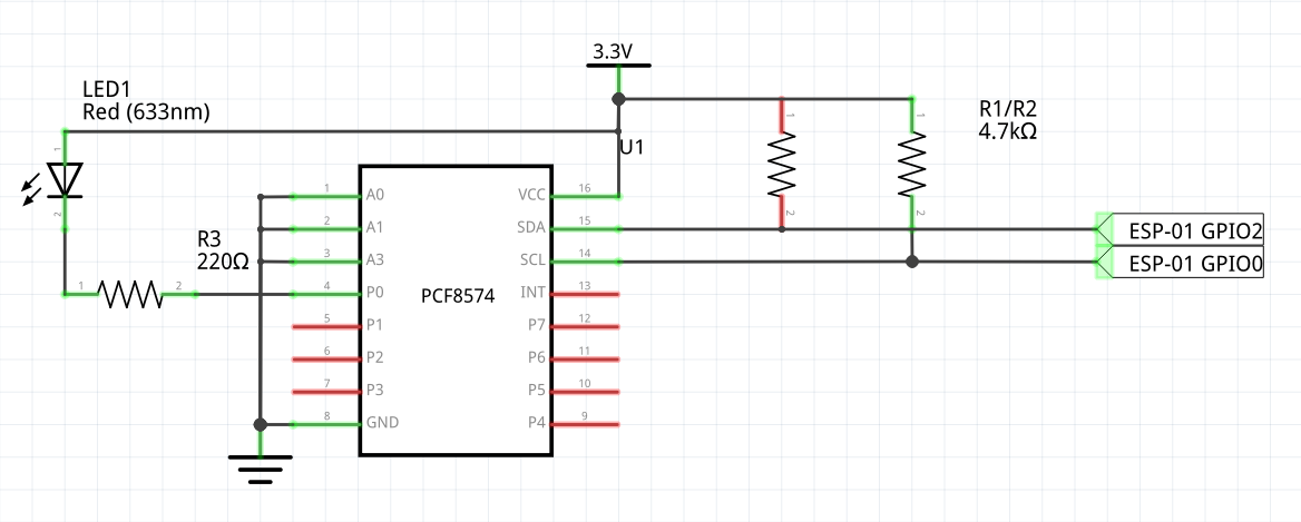
On the ESP-01 board we need to connect the GPIO pins to the I2C bus pins of the PCF8574 chip. In my case I’ve defined the following:
- SDA -> GPIO2 to PCF8574A pin 15
- SCL -> GPIO0 to PCF8574A pin 14
We also need to add pull up resistors from these pins to VCC. I’m using 4K7 resistor. Regarding the address pins (PCF8574A pins 1,2,3), I’ve grounded them all, so the I2C address is the base address for the chip. In my case the chip is the PCF8574A variant which means that the base address is 0x38. If I pull up A0 to VCC, then the address becomes 0x39 for example.
Regarding the address it’s important to note that NodeMcu uses 7 bit addresses and the I2C functions themselves set the LSB (least significant bit) for reading or writing data. So the I2 addresses to use on the I2C functions are the 7 MSB as the addresses as we can see on the PCF8574 datasheet.
The final schema is the following:
After powering up, all PCF8574 pins should be at level high (VCC).
Checking the hardware:
There is an I2C scanner available on the web that allows to check if there are I2C devices present on the I2C bus. For example on this thread there are some Lua script examples: http://www.esp8266.com/viewtopic.php?f=19&t=1049
I’ve used this variation of the script: i2_scan.lua
-- Based on work by sancho and zeroday among many other open source authors
-- This code is public domain, attribution to gareth@l0l.org.uk appreciated.

id=0  -- need this to identify (software) IC2 bus?
gpio_pin= {4,3,0,1,2} -- this array maps internal IO references to GPIO numbers

-- user defined function: see if device responds with ACK to i2c start
function find_dev(i2c_id, dev_addr)
     i2c.start(i2c_id)
     c=i2c.address(i2c_id, dev_addr ,i2c.TRANSMITTER)
     i2c.stop(i2c_id)
     return c
end

print("Scanning all pins for I2C Bus device")
for scl=1,7 do
     for sda=1,7 do
          tmr.wdclr() -- call this to pat the (watch)dog!
          if sda~=scl then -- if the pins are the same then skip this round
               i2c.setup(id,sda,scl,i2c.SLOW) -- initialize i2c with our id and current pins in slow mode :-)
               for i=0,127 do -- TODO - skip invalid addresses
                    if find_dev(id, i)==true then
                    print("Device is wired: SDA to GPIO - IO index "..sda)
                    print("Device is wired: SCL to GPIO - IO index "..scl)
                    print("Device found at address 0x"..string.format("%02X",i))
                    end
               end
          end
     end
end
And the output is:
> dofile('i2c_scan.lua')
Scanning all pins for I2C Bus device
Device is wired: SDA to GPIO - IO index 4
Device is wired: SCL to GPIO - IO index 3
Device found at address 0x38
Nodemcu Lua I2C functions:
To use Nodemcu Lua I2C functions we need the following functions:
- i2.setup ( bus_id , SDA_pin , SCL_pin , I2C_bus_speed) – This function should be called before any other I2C activity. The bus_id parameter is on this case always zero, and the SDA and SCL pins the Nodemcu GPIO pind definition. Check out the Github NodeMcu page for the mappings. In our case the GPIO2 is index 4 and GPIO0 is index 3. The last parameter is the I2C bus speed that always should be i2c.SLOW.
After initializing the i2c functions, we can now read or write to the device. The pattern for this is always the same:
- i2c.start( bus_id ) -> Start the i2c transaction
- i2c.address( bus_id , device_address, operation) -> For our case and for the PCF8574A the device_address is 0x38, and the operation is i2c.RECEIVER for reading data, or i2c.TRANSMITTER for writing data. Based on this parameter the LSB bit is added to the device address to define the operation, 1 for read, zero for writing and thus build the complete 8 bit address. This function also returns values: It returns true if the device acknowledges the operation.
- i2c.read(bus_id, size) -> For the i2c.RECEIVER operation it reads size bytes into a string from the i2c bus. That is the value that is returned from the function.
- i2c.write(bus_id, data) -> For the i2c.TRANSMITTER operation it writes the data on the i2c bus. The value returned is the number of bytes that where wrote.
- i2c.stop(bus_id) -> Stops the i2c transaction.
For more complete information check the Nodemcu LUA api pages, for example: Nodemcu LUA api
Using the PCF8574
Now it is simple to use the I2C PCF8574 port expander from the ESP8266. We know the address and sine it only has one register it is easy to read and write into the chip. One interesting thing if something is written on the pins, the same value can be read if nothing is connected to it. Caution for not short circuiting… Please read the data sheet if wanting to use some pins as inputs.
Anyway, the simple code for blinking a led is the following: pcf8574_blinkled.lua
busid = 0  -- I2C Bus ID. Always zero
sda= 4     -- GPIO2 pin mapping is 4
scl= 3     -- GPIO0 pin mapping is 3

addr=0x38  -- the I2C address of our device
led = 0;
-- Seting up the I2C bus.
i2c.setup(busid,sda,scl,i2c.SLOW)

-- Read from the pcf8574
function read_pcf8574(dev_addr)
     i2c.start(busid)
     i2c.address(busid, dev_addr , i2c.RECEIVER)
     bdata = i2c.read(busid,1)  -- Reads one byte
     i2c.stop(busid)
     return bdata
end

-- Writes to the pcf8574
function write_pcf8574(dev_addr, value)
     i2c.start(busid)
     i2c.address(busid, dev_addr, i2c.TRANSMITTER)
     i2c.write(busid,value)
     i2c.stop(busid)
end

-- timer controller blinking led on pin 0.
function blink_led()
    write_pcf8574( addr,  led )
    if led == 0 then
      led = 0x01
    else
      led = 0
    end
    --print("Blink Led...")
end

-- Main program.
i2c.setup(busid,sda,scl,i2c.SLOW)

for i=1, 254 do
    write_pcf8574( addr,  i )
    tmr.delay(20000)
    result=read_pcf8574(addr)
    print(string.byte(result))
    tmr.wdclr()
end

tmr.alarm(2, 1000, 1, blink_led )
An that’s it. Eight new I/O pins expandable to much more on the ESP8266.
As we can see the read and write functions are quite simple since the PCF8574 chip only has one register. If we have a more complex device like an LCD or sensor, we might need first to write some command an the read the data. For example something like this:
function read_i2cdata(dev_addr, command, numbytes)
     i2c.start(busid)
     i2c.address(busid, dev_addr , i2c.TRANSMITTER)
     i2c.write(busid,command)  -- Sends the command
     i2c.stop(busid)

     i2c.start(busid)
     i2c.address(busid, dev_addr, i2c.RECEIVER)
     data = i2c.read(busid, numbytes)
     i2c.stop(busid)
     return data
end
Since there are so many I2C devices available, using I2C is really the only way of getting the most out of the ESP-01 boards.

An example of a very nicely designed. However, I can not read the port if you connect but- ton. All the time I read the value previously sent. Arduino work for me it properly so it is not hardware. Do you have it somehow?
Regards
Adam
Hi!
I’ve done a quick test, and it works fine for me. Please note that the pins for the PCF8574 to behave as input must have 1 written to them.
Then when reading this happens:
– if floating it reads logic level one
– if connected to VCC it reads logic level one
– if grounded to GND it reads logic level zero.
Some schematics just connect the pin to GND without a pull up resistor. It’s not my case. I use a pull-up resistor.
Something like: VCC——/\/\/\/\—Pin—-/switch——> GND
My code is:
busid = 0 — I2C Bus ID. Always zero
sda= 4 — GPIO2 pin mapping is 4
scl= 3 — GPIO0 pin mapping is 3
addr=0x38 — the I2C address of our device
led = 0;
— Seting up the I2C bus.
i2c.setup(busid,sda,scl,i2c.SLOW)
— Read from the pcf8574
function read_pcf8574(dev_addr)
i2c.start(busid)
i2c.address(busid, dev_addr , i2c.RECEIVER)
bdata = i2c.read(busid,1) — Reads one byte
i2c.stop(busid)
return bdata
end
— Writes to the pcf8574
function write_pcf8574(dev_addr, value)
i2c.start(busid)
i2c.address(busid, dev_addr, i2c.TRANSMITTER)
i2c.write(busid,value)
i2c.stop(busid)
end
write_pcf8574( addr , 0xFF )
function read_inputs()
inx = read_pcf8574( addr )
print(string.byte(inx))
end
tmr.alarm(2, 500, 1, read_inputs )
Super – everything works! Solution to five stars (*****).
I’ve tested it and PCF8574AT brought from China. I just had to change the address on 0x3f.
Thank you for being so quick help.
Adam
Hey, i want to control LCD with PCF8574P but it don’t work, i didn’t use the same code i just replace new in write.
To Drive a LCD with the PCF8574P it really depends how the LCD is connected to the port expander and what type of display it is…
Hello I am using esp 01 and trying to connect atmega16 to the esp thru i2c. When run the i2c scanner code I got the following output. Please let me know where I am going wrong.
Scanning I2C Bus
Device found at address 00
Device found at address 01
Device found at address 02
Device found at address 03
Device found at address 04
Device found at address 05
Device found at address 06
Device found at address 07
Device found at address 08
Device found at address 09
Device found at address 0A
Device found at address 0B
Device found at address 0C
Device found at address 0D
Device found at address 0E
Device found at address 0F
That doesn’t look right for sure. Do you have pull-up resistors on the I2C lines? At leas a 4.7K resistor from each line to the 3.3V power line?
I also had issue with my I2C bus and the ESP-01, but that was bad connections. Otherwise it works fine.
Thank you for the reply. Let me redo all the connections and recheck.
Thanks for this well explained into article on how to configure the ESP-01 for I2C. On a technical note, the main loop is a single task taking ~0.5s. This will crash any open WiFi sockets, so bad news.
The current master and dev builds will happily deliver pretty accurate mSec ticks using the software tmr module, so the best way to implement this is to invert this logic w.r.t. a 20 mSec repeating alarm so that each callback reads the last i request and writes the request for the next. The last one stops the timer and (if necessary) calls the next function in the execution sequence. Nasty, I know but that how you should work within the SDK rules. This will run very stably. No individual task should run for more than 15 mSec. If you are having to execute tmr.wdclr() then don’t expect the WiFi to be working when you are done.
Hi, thanks for the input. If referring to tmr.wdclr() on the I2C scanner, it is indeed a bad solution, but this is just for scanning the I2C bus, and find out if any I2C devices are connected and what address are using.
In a real world program, we should use software state machines, using timers and/or interrupts. The later on the ESP-01 is not possible.
I am one of the committers on the nodeMCU project with my focus on the core engine improvements. We’ve done quite a lot of optimisation over the last 6 months. The latest master and dev versions give you ~45Kb heap at startup and code density is 2/3rds the previous 0.9x versions. I’ve just reworked the gpio module and will be doing the i2c one soon, so if you have any constructive functional suggestions, why not post an issue on the Github repo. 🙂
Hi. Thanks, but I2C on NodeMCU was one of the things that I had no issues what so ever, it just worked fine, so not really any suggestions 🙂
Also as might be aware be reading my half crafted blog, I’ve changed to Sming framework to program on the ESP8266. While this framework is in heavy development, almost all Arduino libraries and sample code work OOTB without many changes and translation to Lua. This is a huge leap in productivity where I don’t need to handle with a new language like Lua, translate libraries or code, and in fact it leverages the Arduino code for both platforms.
Also just a final note, setting the baud rate to 460800 (or higher) to flash to the ESP8266, just takes the same time to deploy code as the ESPlorer/NodeMcu combo.
Still NodeMcu and Lua might be easier to someone that is starting up, so keep the good work 🙂
You mention:
SDA -> GPIO2 to PCF8574A pin 14
SCL -> GPIO0 to PCF8574A pin 13
But the pins are 15 and 14, rather than 14 and 13.
You are right. Corrected! Thanks for input 🙂