MakeBlock STEM mbot Robot – Using nodeJS to control mbot through BLE

A few weeks ago I’ve bought a mbot robot out of curiosity (also as a gift), since they became available at a nearby major electronic retailer and cheaper than buying them online.

The mbot is a robot chassis with two wheels, some external and onboard sensors, including an external ultrasonic sensor, and all this supported on a custom version of Arduino 328 board whish incorporates a motor driver, battery charger and so on. The version that I’ve bought also came with a LED Matrix display where it is possible to draw faces, text and numbers (mbot Face version).

The mbot robot can be controlled or used by either some Android (and IOS) mobile applications, or by using the Scratch programming environment. MakeBlock has a specific mbot version for Scratch called mblock that supports a set of new programming blocks to control the robot. The use of Scratch and mbot makes it ideal combination for teaching kids about programming and robotics.

We caan communicate/interface with mbot either by using an USB cable, or either by Low Power Bluetooth (the mbot BLE version) or through a 2.4GHz radio (the mbot 2.4GHz version). The 2.4Ghz version is more adequate for a classroom environment, since each robot is automatically bounded by radio to the 2.4GHz USB computer stick radio controller, which basically makes it plug and go and no need to fiddle with BLE discovery and bounding.

Anyway, the version that I have is the BLE one, and this post is about how to use NodeJS with the BLE Noble Library to communicate with mbot when using the factory firmware.

Requisites:

To make this work we need to have some requisites first:

Since mbot uses BLE, the computer must support also BLE. In my case I’m using the CSR 4 BLE dongle available on eBay, Ali and so on, to have BLE support on my computer.

The mbot must be loaded with the factory firmware so the this code can work. This is off course just for testing this code.
The factory firmware can be loaded either by using the mblock program when connected by USB cable, or by using the Arduino IDE.

The mbot BLE module is connected to the serial pins of the onboard arduino, so while the factory firmware has a specific interface, nothing stops us from replacing it with our own code and interface. For now we just keep the factory interface that is based on messages that start with 0xFF 0x55 ….

The code was tested on Linux, and it works fine. No idea if it works on windows…

As far it goes today, the NodeJS Bleno library doesn’t work with the latest node version 10, so we need to use this with a previous version of NodeJS. I’m using NodeJS V8, and also use the NodeJS Version Manager to have several versions of NodeJS active and available.

The BLE interface:
Using the Nordic Connect mobile application, we turn on the mbot, and on the application we start the BLE scan:

A device named Makeblock_LE should appear. We can connect to it and see the published services and characteristics:

There are two known services, and two unknown services. After some testing writing data to those services the service ffe1 is the service that connects to the mbot arduino serial port, and the service ffe4 I have no idea what it is for. Probably for controlling something on the BLE module itself.

The characteristics that the service ffe1 service exposes are:

As we can see, on is for reading data: ffe2 and it supports notification. This means we are warned when data is available so we can read it. The other characteristic is ffe3 that is for writing.

Basically if we connect to the Makeblock_LE BLE device, use the ffe1 service and write on the ffe3 characteristic we can control the robot. Data from the robot is automatically sent to us if we have notifications enabled on the ffe2 characteristic.

The mbot protocol:

There is one post that explains the protocol structure to communicate with the mbot.

Basically every command begins with 0xff 0x55 and then a set of bytes to control something.

The responses follow the same principle of starting with 0xff 0x55 and can return several values types.

An easier way to see what to send is to use mblock, program a scratch example in Arduino mode, and on the mblock serial monitor see what is sent to the robot.

My GitHub code source has some command examples for sending to mbot, namely to control the WS2812 RGB leds, the buzzer, the Led Matrix and to read data from the ultrasonic sensor.

How to use it:

Download the code from here MBot_BLE.

git clone https://github.com/fcgdam/mbot_ble

Make sure that you are using NodeJS version 8:

node -v
v8.11.3

If using Node V10, you can try to install the modules since in a future date from this post, the issues with Noble and NodeJS V10 might be solved.

Install the modules dependencies:

npm install

The code to access the BLE device needs root access, or check how to use Noble without root access:

sudo node mbotble.js

If the Ultrasonic distance sensor is connected to port 3, distance data is shown on the terminal.

That’s it!

Sample output:

The sample output for the mbotble.js when running as root on the RPI 3:

root@firefly:/home/pi/BLEMbot# node blembot.js 
- Bluetooth state change
  - Start scanning...
! Found device with local name: Makeblock_LE
! Mbot robot found! 
  - Stopped scanning...
- Connecting to Makeblock_LE [001010F13480]
! Connected to 001010F13480
! mbot BLE service found!
! mbot READ BLE characteristic found.
! mbot WRITE BLE characteristic found.
- End scanning BLE characteristics.
! Subscribed for mbot read notifications
Reading the ultrasound sensor data...
> mbot data received: "ff550002cb3db9410d0a"
Distance: 23.15517234802246
Reading the ultrasound sensor data...
> mbot data received: "ff5500020000bc410d0a"
Distance: 23.5
Reading the ultrasound sensor data...
> mbot data received: "ff5500027c1ab9410d0a"
Distance: 23.13793182373047
Reading the ultrasound sensor data...
> mbot data received: "ff5500028db0c0410d0a"
Distance: 24.086206436157227
Reading the ultrasound sensor data...
> mbot data received: "ff550002ddd398400d0a"
Distance: 4.775862216949463
Reading the ultrasound sensor data...
> mbot data received: "ff5500024f23d8410d0a"
Distance: 27.017240524291992
...
...
...

Skype for Linux – Using corporate proxy

Since, unfortunately, I some times need to use Skype on Linux and because I’m behind a corporate proxy server, Skype doesn’t work or accept, at least on Arch Linux running KDE Plasma desktop, the system proxy settings.

Setting the http_proxy/https_proxy variables have no effect on the Electron (I think…) Skype based app.

Anyway the solution for this is quite simple: Just install ProxyChains.

[pcortex@desktop:~]$ sudo pacman -S proxychains-ng

After installing, edit the file /etc/proxychains.conf and under the [ProxyList] add your proxy:

http  10.1.1.1  3128  my_proxy_username  my_proxy_password

Save the file, and now just run skype with the following command:

[fpcortex@desktop:~]$ proxychains skypeforlinux

Making now the test call works.

Using the Blackmagic probe with Netbeans

Using the Blackmagic debug probe (BMP) with Netbeans is very similar when doing the same but with using Openocd.

The initial steps are the same to use the BMP probe and Openocd. First we set up the ARM toolchain or other, as needed. We also need the gdbserver plugin for Netbeans, and so, we also need to install it. After these two initial steps, the remaining configuration and how to use the probe differs a bit differently from when using Openocd.

One of the main differences is that with Openocd, externally we launch an instance of Openocd and then use the Netbeans gdbserver plugin to connect to that openocd instance. For that we use the Netbeans menu Debug and Attach Debugger and use connection string extended-remote localhost:3333 and the selected project:

For using the BMP probe we don’t need no intermediary software since the code supporting the gdbserver plugin is already on the probe firmware, which means that the debugger can connect directly to the target. In fact due to this we do not need now to attach to a debugger and we can start using the Debug Project (CTRL-F5) to program/flash the code output (optional) and to start debugging the code running on the target device.

For this to happen we need to configure the Debug Command for the project (this must be done for each project if needed) and if wanted we can also configure the Run Command.
Before we are able to do that, we need first to create a command file for the gdb debugger that will pre-execute some commands, namely to attach to the targets probe, before starting the debugging session.

For that I’ve created a file named BMPgdbinit located, in my case, in /opt/ARM:

target extended-remote /dev/ttyACM0
monitor swdp_scan
att 1
load
start
run

This file is invoked by the ARM debugger toolchain (like this: arm-none-eabi-gdb -x /opt/ARM/BMPgdbinit file.out) and it will connect to the Blackmagic probe, that should be located at /dev/ttyACM0, scan the SWD searching for the device, attaches to it, loads/programs the output file, namely the firmware, and starts it. From this point the gdbserver from Netbeans takes control and should stop at the first line of code or the first break point.

So to configure the run command we edit the Project Properties and modify the Run command:

Just define the Run Command as arm-none-eabi-gdb -x /opt/ARM/BMPgdbinit “${OUTPUT_PATH}”

With this configuration we can now press F6 to flash our firmware (because the load command is on the BMPgdbinit file) and run it.

For debugging we need the following configuration:

We must define the Debug Command as ${OUTPUT_PATH} since this will be passed as the arm-none-eabi-gdb file parameter.
We also need to point to the correct location of the BMPgdbinit file.

We can now just press CTRL-F5 to launch a debug session, and again, the firmware will be loaded, and the code will stop at the first break point.

An example of using Netbeans to build a simple program targeting the nRF52832 (the blinky example from pcbreflux ) with an added variable and a watch point set:

That’s it….

Issues:

There are some issues with the above process…

Can’t stop the debugger. Pressing Pause does nothing…
This is a long standing bug apparently so the solution is on a external terminal window send a SIGINT signal to the gdb process:

[pcortex@pcortex:~]$ ps -ef | grep arm-none
pcortex 9792  9405  0 20:22 ?        00:00:00 /tmp/dlight_fdam/5fe1c993/0397644155/pty --dir /opt/nordic/nRF52832/blinky --no-pty /opt/ARM/gcc-arm-none-eabi-6_2-2016q4/bin/arm-none-eabi-gdb -x /opt/ARM/BMPgdbinit -nx --interpreter mi -tty /dev/pts/7
pcortex 9794  9792  0 20:22 ttyACM0  00:00:00 /opt/ARM/gcc-arm-none-eabi-6_2-2016q4/bin/arm-none-eabi-gdb -x /opt/ARM/BMPgdbinit -nx --interpreter mi -tty /dev/pts/7
 

Just send a SIGINT signal to the process associated to the Blackmagic probe:

kill -SIGINT 9794

The control is returned to Netbeans.

The debugger doesn’t seem to follow my code…
Just Clean and build all the project and select run so a clean version of the program is flashed.

I unplug and plug the probe a lot and the tty ports change..

Because of this the BMPgdbinit script can be broken because the probe port changes, for example, to /dev/ttyACM2.

The solution is to create a rules file:

Mine, for Arch Linux is as follows:

# Black Magic Probe
# there are two connections, one for GDB and one for uart debugging
  SUBSYSTEM=="tty", ATTRS{interface}=="Black Magic GDB Server", SYMLINK+="ttyBMP"
  SUBSYSTEM=="tty", ATTRS{interface}=="Black Magic UART Port", SYMLINK+="ttyBMPUART"

This file is named 99-blackmagic.rules located at /etc/udev/rules.d.

We now need to change the port used on the BMPgdbinit file from /dev/ttyACM0 to /dev/ttyBMP. Note that after plugging in the probe to the USB port, it takes a while (2 to 3 seconds) to the ports appear.

This just doesn’t work…

Yes, some times the behaviour seems strange… I’ve worked around some of the issues by flashing again the softdevice and the program mannually from the GDB command line.

Also if something like this happens:

It is due to the fact that the Netbeans environment variables $OUTPUT_PATH is empty… The solution is to explicitly state the outputfile on the RUN and Debug commands instead of using the ENV var. For example change this:

arm-none-eabi-gdb -x /opt/ARM/BMPgdbinit "${OUTPUT_PATH}"

to this

arm-none-eabi-gdb -x /opt/ARM/BMPgdbinit /opt/Projects/nRF/proj1/program.out

or to this:

arm-none-eabi-gdb -x /opt/ARM/BMPgdbinit "${PROJECT_DIR}/file.out"

Final note:
As a final note, some other errors might creep up like:

  • Program is not being run: Check the command line of arm-none-eabi-gdb to see if the BMPgdbinit file is correctly provided.
  • Don’t know how to run. Try \”help target\”.: Same issue. Check if the run and debug commands are correctly defined.
  • Sometimes my target isn’t detected.: Adding an extra monitor swdp_scan line to the BMPgdbinit file might help.

Building a Blackmagic Debug Probe

The Black Magic debug probe is in-application debugger, which allows IDE’s like NetBeans, Eclipse or others to connect directly to the hardware without using bridges like for example Openocd. The Blackmagic Probe software is open source and available on this Github link.

There are several posts/instructions on the internet regarding how to load the Black Magic firmware either on ST-Link hardware debuggers, ST-Link clones or using the “blue pill” STM32F103C8T6 based board.

There are several possible issues with this board:

  1. First they are quite cheap – not an issue
  2. It seems on some versions there is a problem with the USB connector regarding a resistor and bad contacts. In my version I had no issues. It just worked fine.
  3. The on board chip is the STM32F103C8T6 which has 64Kb of flash, but some claim that it can have 128Kb. In my case all the boards that I have, the flash size is 64Kb.

This last issue is a show stopper at the current release of the Black Magic firmware since it won’t fit on the 64Kb flash of the ST32F103C8T6. We must cut things from the firmware to be able to flash it on the STM32F103C8T6 board. But we will see how to do that.

Downloading and compiling the firmware:
This step is just straight forward, just clone the Blacmagic repository and compile. Since we are compiling to ST32F103 board we will assume it is a ST-Link clone.

[pcortex@pcortex:opt]$ git clone https://github.com/blacksphere/blackmagic
Cloning into 'blackmagic'...
remote: Counting objects: 5029, done.
remote: Compressing objects: 100% (9/9), done.
remote: Total 5029 (delta 1), reused 2 (delta 0), pack-reused 5020
Receiving objects: 100% (5029/5029), 2.01 MiB | 1.38 MiB/s, done.
Resolving deltas: 100% (3558/3558), done.
[pcortex@pcortex:opt]$ cd blackmagic/
README.md  Makefile  libopencm3/  HACKING  driver/  COPYING  scripts/  src/  upgrade/
[pcortex@pcortex:blackmagic|master]$ make
Initialising git submodules...
Submodule 'libopencm3' (https://github.com/libopencm3/libopencm3.git) registered for path 'libopencm3'
Cloning into '/opt/lixo/blackmagic/libopencm3'...
Submodule path 'libopencm3': checked out '67242de60dec0227739cd549e8a78e1a3c15dbf5'
  GENHDR  include/libopencm3/efm32/efm32gg/irq.json
  GENHDR  include/libopencm3/efm32/efm32g/irq.json
  GENHDR  include/libopencm3/efm32/efm32lg/irq.json
  GENHDR  include/libopencm3/efm32/efm32tg/irq.json
  GENHDR  include/libopencm3/stm32/f2/irq.json
...
...
...

Now we must target the firmware to our blue pill board, and so compiling the firmware as it was for a ST-Link clone:

[pcortex@pcortex:blackmagic|master]$ cd src
[pcortex@pcortex:src|master]$ make clean
 CLEAN
[pcortex@pcortex:src|master]$ make PROBE_HOST=stlink
GIT     include/version.h
  CC      target/adiv5.c
  CC      target/adiv5_jtagdp.c
  CC      target/adiv5_swdp.c
  CC      command.c
  CC      target/cortexa.c
  CC      target/cortexm.c
...
...
...
  CC      platforms/stlink/dfu_upgrade.c
  LD      dfu_upgrade
  OBJCOPY dfu_upgrade.bin
  OBJCOPY dfu_upgrade.hex

Done! On the src there is now at least two files:

  1. blackmagic_dfu.bin – The Device Firmware Upgrade loader.
  2. blackmagic.bin – The Blackmagic firmware.

Checking the file sizes we can see that the blackmagic.bin file (as of today) 57K, and the bootloader is 6.8K.

Flashing the firmware:
Flashing the firmware can be done by several forms:

  1. Using the STM32 embedded loader through a serial port
  2. Using the SWD connection, ST-Link probe and Openocd
  3. Using the SWD connection, ST-Link probe and Texane/st-link/st-util
  4. Using the DFU protocol, but it depends if the board already has a DFU firmware loaded.

Most of the posts on the internet regarding this step use the first aproach, namely using the STM32 boot loader and serial port. This needs a serial to USB converter to be connected and the STM32 boot pins to be modified.

Anyway, I’m flashing the firmware using Openocd and/or st-link utils through a ST-Link debug probe:

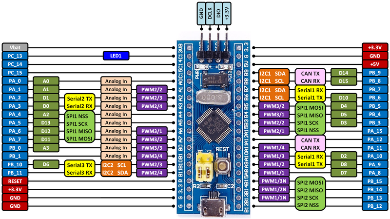
The blue pill pinout is as follows where the SWD connector is oposite the USB port:

From the ST-Link probe we need to connect the following pins:

  • Probe SWCLK Blue Pill DCLK
  • Probe SWDIO Blue Pill DIO
  • Probe GND Blue Pill GND

Regarding the power, I advise not to connect it and power up the blue pill board through the USB connector. This will allow to have access to both boards through USB without any possible power clashes.

We can now flash the firmware either with Texane St-Link programs or the AUR Arch Linux package stlink-git or using Openocd.

For using Openocd, create the following file and name it for example bluepill.cfg:

set CHIPNAME STM32F103C8T6

source [find interface/stlink-v2.cfg]
transport select hla_swd
source [find target/stm32f1x.cfg]
set WORKAREASIZE 0x2000

Also make sure that the ST-Link probe is detected so both st-link utils and openocd can work:

[pcortex@pcortex:src|master]$ lsusb
Bus 002 Device 003: ID 05e3:0608 Genesys Logic, Inc. Hub
Bus 002 Device 001: ID 1d6b:0002 Linux Foundation 2.0 root hub
Bus 008 Device 003: ID 046d:c52f Logitech, Inc. Unifying Receiver
Bus 008 Device 002: ID 0a12:0001 Cambridge Silicon Radio, Ltd Bluetooth Dongle (HCI mode)
...
Bus 003 Device 008: ID 0483:3748 STMicroelectronics ST-LINK/V2

We can now flash our board with the following command using Openocd:

openocd -f ../bluepill.cfg -c ‘init_reset halt; program blackmagic_dfu.bin 0x8000000 verify; reset;exit’

[pcortex@pcortex:src|master]$ openocd -f ../bluepill.cfg -c 'init_reset halt; program blackmagic_dfu.bin 0x8000000 verify; reset;exit'
Open On-Chip Debugger 0.10.0
Licensed under GNU GPL v2
For bug reports, read
        http://openocd.org/doc/doxygen/bugs.html
Info : The selected transport took over low-level target control. The results might differ compared to plain JTAG/SWD
adapter speed: 1000 kHz
adapter_nsrst_delay: 100
none separate
0x2000
Info : Unable to match requested speed 1000 kHz, using 950 kHz
Info : clock speed 950 kHz
Info : STLINK v2 JTAG v24 API v2 SWIM v4 VID 0x0483 PID 0x3748
Info : using stlink api v2
Info : Target voltage: 3.208372
Info : STM32F103C8T6.cpu: hardware has 6 breakpoints, 4 watchpoints
target halted due to debug-request, current mode: Thread 
xPSR: 0x01000000 pc: 0x080017b4 msp: 0x20005000
** Programming Started **
auto erase enabled
Info : device id = 0x20036410
Info : flash size = 64kbytes
target halted due to breakpoint, current mode: Thread 
xPSR: 0x61000000 pc: 0x2000003a msp: 0x20005000
wrote 7168 bytes from file blackmagic_dfu.bin in 0.656939s (10.655 KiB/s)
** Programming Finished **
** Verify Started **
target halted due to breakpoint, current mode: Thread 
xPSR: 0x61000000 pc: 0x2000002e msp: 0x20005000
verified 6900 bytes in 0.187018s (36.030 KiB/s)
** Verified OK **
[pcortex@pcortex:src|master]$

Using the st-flash command as documented on STM as BMP

[pcortex@pcortex:src|master]$ st-flash write blackmagic_dfu.bin 0x8000000
st-flash 1.3.1
2017-06-13T20:26:01 INFO src/common.c: Loading device parameters....
2017-06-13T20:26:01 INFO src/common.c: Device connected is: F1 Medium-density device, id 0x20036410
2017-06-13T20:26:01 INFO src/common.c: SRAM size: 0x5000 bytes (20 KiB), Flash: 0x10000 bytes (64 KiB) in pages of 1024 bytes
2017-06-13T20:26:01 INFO src/common.c: Attempting to write 6888 (0x1ae8) bytes to stm32 address: 134217728 (0x8000000)
Flash page at addr: 0x08001800 erased
2017-06-13T20:26:01 INFO src/common.c: Finished erasing 7 pages of 1024 (0x400) bytes
2017-06-13T20:26:01 INFO src/common.c: Starting Flash write for VL/F0/F3 core id
2017-06-13T20:26:01 INFO src/flash_loader.c: Successfully loaded flash loader in sram
  6/6 pages written
2017-06-13T20:26:02 INFO src/common.c: Starting verification of write complete
2017-06-13T20:26:02 INFO src/common.c: Flash written and verified! jolly good!
[pcortex@pcortex:src|master]$

So far so good, but the above is just DFU firmware that allows to use DFU utils later to upgrade the firmware through the USB port without using any other tools.

If unplug and plug our blue pill board and check for the USB ports we have now:

[pcortex@pcortex:src|master]$ lsusb
Bus 002 Device 003: ID 05e3:0608 Genesys Logic, Inc. Hub
Bus 002 Device 001: ID 1d6b:0002 Linux Foundation 2.0 root hub
Bus 008 Device 003: ID 046d:c52f Logitech, Inc. Unifying Receiver
Bus 008 Device 002: ID 0a12:0001 Cambridge Silicon Radio, Ltd Bluetooth Dongle (HCI mode)
...
Bus 003 Device 012: ID 1d50:6017 OpenMoko, Inc. Black Magic Debug Probe (DFU)
Bus 003 Device 008: ID 0483:3748 STMicroelectronics ST-LINK/V2
...

And we can now also use the dfu-util command to upload the firmware.

To upload the firmware we will see that it fails due to the firmware size and the 64Kb flash size. It might not happen to you if your board has more than 64Kb of flash available.

With Openocd command:

openocd -f ../bluepill.cfg -c 'init_reset halt; program blackmagic.bin verify; reset;exit'    
Open On-Chip Debugger 0.10.0
Licensed under GNU GPL v2
For bug reports, read
        http://openocd.org/doc/doxygen/bugs.html
Info : The selected transport took over low-level target control. The results might differ compared to plain JTAG/SWD
adapter speed: 1000 kHz
adapter_nsrst_delay: 100
none separate
0x2000
Info : Unable to match requested speed 1000 kHz, using 950 kHz
Info : clock speed 950 kHz
Info : STLINK v2 JTAG v24 API v2 SWIM v4 VID 0x0483 PID 0x3748
Info : using stlink api v2
Info : Target voltage: 3.208372
Info : STM32F103C8T6.cpu: hardware has 6 breakpoints, 4 watchpoints
target halted due to debug-request, current mode: Thread 
xPSR: 0x01000000 pc: 0x080017b4 msp: 0x20005000
** Programming Started **
auto erase enabled
Info : device id = 0x20036410
Info : flash size = 64kbytes
Warn : no flash bank found for address 0
wrote 0 bytes from file blackmagic.bin in 0.016043s (0.000 KiB/s)
** Programming Finished **
** Verify Started **
target halted due to breakpoint, current mode: Thread 
xPSR: 0x61000000 pc: 0x2000002e msp: 0x20005000
Error: checksum mismatch - attempting binary compare
diff 0 address 0x08010000. Was 0xff instead of 0x00
diff 1 address 0x08010001. Was 0xff instead of 0x00
diff 2 address 0x08010002. Was 0xff instead of 0x00
diff 3 address 0x08010003. Was 0xff instead of 0x00
diff 4 address 0x08010004. Was 0xff instead of 0x00
diff 5 address 0x08010005. Was 0xff instead of 0x00
diff 6 address 0x08010006. Was 0xff instead of 0x00

....
diff 123 address 0x0801007b. Was 0xff instead of 0x00
diff 124 address 0x0801007c. Was 0xff instead of 0x00
diff 125 address 0x0801007d. Was 0xff instead of 0x00
diff 126 address 0x0801007e. Was 0xff instead of 0x00
diff 127 address 0x0801007f. Was 0xff instead of 0x00
More than 128 errors, the rest are not printed.
embedded:startup.tcl:476: Error: ** Verify Failed **
in procedure 'program' 
in procedure 'program_error' called at file "embedded:startup.tcl", line 520
at file "embedded:startup.tcl", line 476

With the st-flash command:

[pcortex@pcortex:src|master]$ st-flash --reset write blackmagic.bin 0x8002000
st-flash 1.3.1
2017-06-13T20:37:27 INFO src/common.c: Loading device parameters....
2017-06-13T20:37:27 INFO src/common.c: Device connected is: F1 Medium-density device, id 0x20036410
2017-06-13T20:37:27 INFO src/common.c: SRAM size: 0x5000 bytes (20 KiB), Flash: 0x10000 bytes (64 KiB) in pages of 1024 bytes
2017-06-13T20:37:27 INFO src/common.c: Attempting to write 58084 (0xe2e4) bytes to stm32 address: 134225920 (0x8002000)
2017-06-13T20:37:27 ERROR src/common.c: addr too high
stlink_fwrite_flash() == -1
[pcortex@pcortex:src|master]$ 

And with the dfu util forcing the write above 64Kb:

[pcortex@pcortex:src|master]$ sudo dfu-util -a 0 -s 0x08002000:leave:force -D blackmagic.bin
dfu-util 0.9

Copyright 2005-2009 Weston Schmidt, Harald Welte and OpenMoko Inc.
Copyright 2010-2016 Tormod Volden and Stefan Schmidt
This program is Free Software and has ABSOLUTELY NO WARRANTY
Please report bugs to http://sourceforge.net/p/dfu-util/tickets/

dfu-util: Invalid DFU suffix signature
dfu-util: A valid DFU suffix will be required in a future dfu-util release!!!
Opening DFU capable USB device...
ID 1d50:6017
Run-time device DFU version 011a
Claiming USB DFU Interface...
Setting Alternate Setting #0 ...
Determining device status: state = dfuIDLE, status = 0
dfuIDLE, continuing
DFU mode device DFU version 011a
Device returned transfer size 1024
DfuSe interface name: "Internal Flash   "
Downloading to address = 0x08002000, size = 58084
dfu-util: Last page at 0x080102e3 is not writeable
[pcortex@pcortex:src|master]$ 

So no luck with my board version, and as a solution we need to strip down the firmware.

Striping down the firmware:
To make the BMP firmware able to fit the 64Kb flash we have to cut things. In my case I’ve removed some processors support since my work is with the STM32 and nRF families:

Edit the file named cortexm.c located at target subdirectory, and delete the following lines around line 254 (or search by PROBE) to remove the unneeded support:

#define PROBE(x) \
        do { if ((x)(t)) return true; else target_check_error(t); } while (0)

        PROBE(stm32f1_probe);
        PROBE(stm32f4_probe);
        PROBE(stm32l0_probe);   /* STM32L0xx & STM32L1xx */
        PROBE(stm32l4_probe);
        PROBE(lpc11xx_probe);
        PROBE(lpc15xx_probe);
        PROBE(lpc43xx_probe);
        PROBE(sam3x_probe);
        PROBE(sam4l_probe);
        PROBE(nrf51_probe);
        PROBE(samd_probe);
        PROBE(lmi_probe);
        PROBE(kinetis_probe);
        PROBE(efm32_probe);

Still at the source directory we build again the firmware:

[pcortex@pcortex:src|master]$ make clean
[pcortex@pcortex:src|master]$ make PROBE_HOST=stlink
[pcortex@pcortex:src|master]$ ls -l blackmagic*
-rwxr-xr-x 1 pcortex users 753K jun 13 20:53 blackmagic*
-rwxr-xr-x 1 pcortex users  55K jun 13 20:53 blackmagic.bin*
-rwxr-xr-x 1 pcortex users 325K jun 13 20:53 blackmagic_dfu*
-rwxr-xr-x 1 pcortex users 6,8K jun 13 20:53 blackmagic_dfu.bin*
-rw-r--r-- 1 pcortex users  20K jun 13 20:53 blackmagic_dfu.hex
[pcortex@pcortex:src|master]$

We can seen now that the firmware was “slim down” around 2K, which is enough now to fit the 64Kb flash:

Using Openocd:

[pcortex@pcortex:src|master]$ openocd -f ../bluepill.cfg -c 'init_reset halt; program blackmagic.bin 0x8002000 verify; reset;exit'
Open On-Chip Debugger 0.10.0
Licensed under GNU GPL v2
For bug reports, read
        http://openocd.org/doc/doxygen/bugs.html
Info : The selected transport took over low-level target control. The results might differ compared to plain JTAG/SWD
adapter speed: 1000 kHz
adapter_nsrst_delay: 100
none separate
0x2000
Info : Unable to match requested speed 1000 kHz, using 950 kHz
Info : clock speed 950 kHz
Info : STLINK v2 JTAG v24 API v2 SWIM v4 VID 0x0483 PID 0x3748
Info : using stlink api v2
Info : Target voltage: 3.208372
Info : STM32F103C8T6.cpu: hardware has 6 breakpoints, 4 watchpoints
target halted due to debug-request, current mode: Thread 
xPSR: 0x01000000 pc: 0x080017b4 msp: 0x20005000
** Programming Started **
auto erase enabled
Info : device id = 0x20036410
Info : flash size = 64kbytes
target halted due to breakpoint, current mode: Thread 
xPSR: 0x61000000 pc: 0x2000003a msp: 0x20005000
wrote 54272 bytes from file blackmagic.bin in 3.792976s (13.973 KiB/s)
** Programming Finished **
** Verify Started **
target halted due to breakpoint, current mode: Thread 
xPSR: 0x61000000 pc: 0x2000002e msp: 0x20005000
verified 53744 bytes in 0.854957s (61.388 KiB/s)
** Verified OK **

Using st-flash:

[pcortex@pcortex:src|master]$ st-flash --reset write blackmagic.bin 0x8002000
st-flash 1.3.1
2017-06-13T20:58:02 INFO src/common.c: Loading device parameters....
2017-06-13T20:58:02 INFO src/common.c: Device connected is: F1 Medium-density device, id 0x20036410
2017-06-13T20:58:02 INFO src/common.c: SRAM size: 0x5000 bytes (20 KiB), Flash: 0x10000 bytes (64 KiB) in pages of 1024 bytes
2017-06-13T20:58:02 INFO src/common.c: Attempting to write 55720 (0xd9a8) bytes to stm32 address: 134225920 (0x8002000)
Flash page at addr: 0x0800f800 erased
2017-06-13T20:58:05 INFO src/common.c: Finished erasing 55 pages of 1024 (0x400) bytes
2017-06-13T20:58:05 INFO src/common.c: Starting Flash write for VL/F0/F3 core id
2017-06-13T20:58:05 INFO src/flash_loader.c: Successfully loaded flash loader in sram
 54/54 pages written
2017-06-13T20:58:09 INFO src/common.c: Starting verification of write complete
2017-06-13T20:58:09 INFO src/common.c: Flash written and verified! jolly good!

Using the DFU firmware upload:

[pcortex@pcortex:src|master]$ sudo dfu-util -a 0 -s 0x08002000:leave:force -D blackmagic.bin
dfu-util 0.9

Copyright 2005-2009 Weston Schmidt, Harald Welte and OpenMoko Inc.
Copyright 2010-2016 Tormod Volden and Stefan Schmidt
This program is Free Software and has ABSOLUTELY NO WARRANTY
Please report bugs to http://sourceforge.net/p/dfu-util/tickets/

dfu-util: Invalid DFU suffix signature
dfu-util: A valid DFU suffix will be required in a future dfu-util release!!!
Opening DFU capable USB device...
ID 1d50:6017
Run-time device DFU version 011a
Claiming USB DFU Interface...
Setting Alternate Setting #0 ...
Determining device status: state = dfuIDLE, status = 0
dfuIDLE, continuing
DFU mode device DFU version 011a
Device returned transfer size 1024
DfuSe interface name: "Internal Flash   "
Downloading to address = 0x08002000, size = 55720
Download        [=========================] 100%        55720 bytes
Download done.
File downloaded successfully
Transitioning to dfuMANIFEST state

And now if we unplug the blue pill board and connect it again we should have two new tty USB based ports:

[35014.003313] usb 3-2.4: new full-speed USB device number 20 using uhci_hcd
[35019.346373] cdc_acm 3-2.4:1.0: ttyACM0: USB ACM device
[35019.349364] cdc_acm 3-2.4:1.2: ttyACM1: USB ACM device

Success!

Starting using the BMP probe:

To start using our blue pill board as a Blackmagic probe we need the following information and configuration:

  1. Connect a LED (with a resistor…) to pin PA8 to show the probe activity.
  2. The target SWD pins are CLK at pin PA5 and DIO at PB14.
  3. The support for the USB to UART bridge (the second ttyACM1 port) is PA3 – RX and PA2 – TX

So we now can use the BM probe instead of a ST-Link probe, and connect the target board SWD pins to PA5 e PB14: CLK and DIO respectively.

The led will blink when the program is running or it will fast blink when loading a program into the target board.

More information on this video from no other than the builder of the Magic Probe to see more of the probe capabilities. I also recommend the Blackmagic probe wiki for further information.

A quick example with an nRF52 based board connected to the BMP by using the ARM GDB debugger arm-none-eabi-gdb directly:

(gdb) target extended-remote /dev/ttyACM0
Remote debugging using /dev/ttyACM0
(gdb) monitor swdp_scan
Target voltage: unknown
Available Targets:
No. Att Driver
 1      Nordic nRF52
(gdb) att 1
(gdb) monitor
Black Magic Probe (Firmware v1.6.1-25-gaaa7b0e-dirty) (Hardware Version 0)
Copyright (C) 2015  Black Sphere Technologies Ltd.
License GPLv3+: GNU GPL version 3 or later 


Interesting links:

Most of this post wouldn’t be possible without gathering information from around the web. Here is a set of information that might be useful to gather more or missing information from this post:

  1. Black Magic Probe (BMP) on ST-Link v2 clones
  2. STM Discovery as Black Magic Probe
  3. STM32Duino forum

Setting up Openocd for programming the Nordic nRF52832 chip

The following post organizes a set of information gathered from around the web to allow the use openocd utility to also program/access the nRF52 based chips.

Openocd must be patched to be used against the nRF52832 chip. Most of the required information is on this pcbreflux post.

Retriving the sources and patchs
At least, at the current date, on Arch Linux, Openocd version is 0.10. We will keep this version and install side by side the patched version of Openocd that supports the NRF52 chip.

First let’s retrieve the code and patchs:

[pcortex@pcortex:opt]$ git clone git://git.code.sf.net/p/openocd/code openocd-code
Cloning into 'openocd-code'...
remote: Counting objects: 55979, done.
remote: Compressing objects: 100% (20335/20335), done.
remote: Total 55979 (delta 46033), reused 43114 (delta 35495)
Receiving objects: 100% (55979/55979), 12.54 MiB | 2.88 MiB/s, done.
Resolving deltas: 100% (46033/46033), done.
[pcortex@pcortex:opt]$ cd openocd-code
[pcortex@pcortex:openocd-code|master]$ git pull http://openocd.zylin.com/openocd refs/changes/15/3215/2
remote: Counting objects: 1482, done
remote: Finding sources: 100% (11/11)
remote: Total 11 (delta 0), reused 2 (delta 0)
Unpacking objects: 100% (11/11), done.
From http://openocd.zylin.com/openocd
 * branch              refs/changes/15/3215/2 -> FETCH_HEAD
Auto-merging src/flash/nor/drivers.c
CONFLICT (content): Merge conflict in src/flash/nor/drivers.c
Auto-merging src/flash/nor/Makefile.am
CONFLICT (content): Merge conflict in src/flash/nor/Makefile.am
Automatic merge failed; fix conflicts and then commit the result.
[pcortex@pcortex:openocd-code|master *+|MERGING]$ 

After this we have two conflicting files that have changes that we must deal manually.

The src/flash/nor/drivers.c merge conflict is easy to solve. The conflict error is due to clash between empty sections and some added code lines. The end result file is here.

The Makefile.am takes more work to merge, but it is available -> here <- with the merges done.

Then, for specifically support the nRF52832 chip which has 512Kb of flash we need to change the openocd-code/src/flash/nor/nrf52.c currently on line 133, by adding the chip information:

static const struct nrf52_device_spec nrf52_known_devices_table[] = {
	{
		.hwid   = 0x0053,
		.variant  = "QFAA",
		.build_code = "AA",
		.flash_size_kb  = 512,
	},
{
                .hwid        = 0x00C7,
                .variant    = "QFN48",
                .build_code    = "B00",
                .flash_size_kb    = 512,
    	},
};

Done!

We just need now to compile:

    cd /opt/openocd-code/
    ./bootstrap
    ./configure
    make

In my case I just didn’t executed the last sudo make install since I want to have two versions of Openocd side by side.

We should have now at /opt/openocd-code/src the openocd binary with the patchs:

[pcortex@pcortex:src|master *+|MERGING]$ ./openocd -v
Open On-Chip Debugger 0.10.0+dev-00146-g1025be36-dirty (2017-06-04-10:06)
Licensed under GNU GPL v2
For bug reports, read
        http://openocd.org/doc/doxygen/bugs.html

Connecting to the nRF52832 using ST-Link

We can now use this version to connect to the nRF52 chip.
A sample openocd config file can be as follows:

nRF52832.cfg

#nRF52832 Target
source [find interface/stlink-v2.cfg]

transport select hla_swd

source [find target/nrf52.cfg]

But since I did not run the sudo make install command the tcl files from the Arch Linux package are different from the patched version, so it is important that the patched version also uses the patched/new files:

./openocd -s /opt/openocd-code/tcl -f nRF52832.cfg

The expected output:

Open On-Chip Debugger 0.10.0+dev-00146-g1025be36-dirty (2017-06-04-10:06)
Licensed under GNU GPL v2
For bug reports, read
        http://openocd.org/doc/doxygen/bugs.html
Info : The selected transport took over low-level target control. The results might differ compared to plain JTAG/SWD
adapter speed: 10000 kHz
Info : Unable to match requested speed 10000 kHz, using 4000 kHz
Info : clock speed 4000 kHz
Info : STLINK v2 JTAG v21 API v2 SWIM v4 VID 0x0483 PID 0x3748
Info : using stlink api v2
Info : Target voltage: 3.261252
Info : nrf52.cpu: hardware has 6 breakpoints, 4 watchpoints

We should be able now to run the nrf52 command:

telnet localhost 4444
Trying ::1...
Connection failed: Connection refused
Trying 127.0.0.1...
Connected to localhost.
Escape character is '^]'.
Open On-Chip Debugger
> nrf52
nrf52
  nrf52 mass_erase
nrf52.cpu
  nrf52.cpu arm
    nrf52.cpu arm core_state ['arm'|'thumb']
...

And programming:

> program /opt/nRF5_SDK_12.3.0_d7731ad/examples/ble_peripheral/ble_app_uart/hex/ble_app_uart_pca10028_s130.hex verify
target halted due to debug-request, current mode: Thread 
xPSR: 0x01000000 pc: 0x000006d0 msp: 0x000007c0
** Programming Started **
auto erase enabled
nRF51822-QFN48(build code: B00) 512kB Flash
Padding image section 0 with 2112 bytes
Padding image section 1 with 32 bytes
using fast async flash loader. This is currently supported
only with ST-Link and CMSIS-DAP. If you have issues, add
"set WORKAREASIZE 0" before sourcing nrf52.cfg to disable it
target halted due to breakpoint, current mode: Thread 
xPSR: 0x61000000 pc: 0x2000001e msp: 0x000007c0
wrote 126976 bytes from file /opt/nRF5_SDK_12.3.0_d7731ad/examples/ble_peripheral/ble_app_uart/hex/ble_app_uart_pca10028_s130.hex in 3.972911s (31.211 KiB/s)
** Programming Finished **
** Verify Started **
target halted due to breakpoint, current mode: Thread 
xPSR: 0x61000000 pc: 0x2000002e msp: 0x000007c0
target halted due to breakpoint, current mode: Thread 
xPSR: 0x61000000 pc: 0x2000002e msp: 0x000007c0
target halted due to breakpoint, current mode: Thread 
xPSR: 0x61000000 pc: 0x2000002e msp: 0x000007c0
verified 121752 bytes in 1.346008s (88.334 KiB/s)
** Verified OK **
> reset run

Remember, if programming fails, with the program command, check if the correct path is provided for openocd through the -s switch.

Done!

NodeJS BLE Applications using BLENO on Arch Linux

BLENO is a greate NodeJS based library for building applications that communicat with other devices (Smartphones, tables, sensor tags) using Bluetooth Low Energy (BLE).

This post is just to quickly document some requirements for successfully use the BLENO library, in my case, on Arch Linux running the latest Plasma (KDE) desktop.

The tools:

Most the information available on the internet for using and controlling the bluetooth adapter uses the now deprecated tools hcitool, hciconfig and so on. Check here the deprecated list of commands.

So we need to use the new tools from the latest Bluez (Bluetooth Linux implementation): btmgm, btinfo, …

Making Bleno examples work:

The simplest example to try out the BLENO library is the battery example located at: […]/bleno/examples/battery-service

First let’s check if our computer/laptop bluetooth adapter is available: Note that all commands must be ran as the root user:

root@pcortex:/opt/bleno/examples/battery-service# btinfo local
Bluetooth information utility ver 5.45
Failed to open HCI user channel
root@pcortex:/opt/bleno/examples/battery-service# 

This issue can be circumvented by stopping the higher level bluetooth stack:

root@pcortex:/opt/bleno/examples/battery-service# systemctl stop bluetooth
root@pcortex:/opt/bleno/examples/battery-service# btinfo local
Bluetooth information utility ver 5.45
HCI version: 6
HCI revision: 7869
LMP version: 6
LMP subversion: 64512
Manufacturer: 2
root@pcortex:/opt/bleno/examples/battery-service#

In case of previously disabling the Bluetooth through the graphical interface:

Disabling the Bluetooth here will have this behaviour (in this case the bluetooth service is still running):

root@pcortex:/opt/bleno/examples/battery-service# systemctl start bluetooth   (<- After this disable bluetooth on the graphical interface)
root@pcortex:/opt/bleno/examples/battery-service# btinfo local
Bluetooth information utility ver 5.45
Failed to open HCI user channel
root@pcortex:/opt/bleno/examples/battery-service# btmgmt power on
Set Powered for hci0 failed with status 0x12 (Blocked through rfkill)
root@pcortex:/opt/bleno/examples/battery-service# 

Even stopping the Bluetooth service keeps the BT adapter disabled:

root@pcortex:/opt/bleno/examples/battery-service# systemctl stop bluetooth
root@pcortex:/opt/bleno/examples/battery-service# btmgmt power on
Set Powered for hci0 failed with status 0x12 (Blocked through rfkill)
root@pcortex:/opt/bleno/examples/battery-service#

We can check this with the rfkill command:

root@pcortex:/opt/bleno/examples/battery-service# rfkill list
0: phy0: Wireless LAN
        Soft blocked: no
        Hard blocked: no
2: hci0: Bluetooth
        Soft blocked: yes
        Hard blocked: no
root@pcortex:/opt/bleno/examples/battery-service# 

We can unblock now the adapter:

root@pcortex:/opt/bleno/examples/battery-service# rfkill unblock 2
root@pcortex:/opt/bleno/examples/battery-service# rfkill list
0: phy0: Wireless LAN
        Soft blocked: no
        Hard blocked: no
2: hci0: Bluetooth
        Soft blocked: no
        Hard blocked: no
root@pcortex:/opt/bleno/examples/battery-service# btinfo local
Bluetooth information utility ver 5.45
HCI version: 6
HCI revision: 7869
LMP version: 6
LMP subversion: 64512
Manufacturer: 2
root@pcortex:/opt/bleno/examples/battery-service# btmgmt power on
hci0 class of device changed: 0x00010c
hci0 Set Powered complete, settings: powered bondable ssp br/edr le secure-conn 
root@pcortex:/opt/bleno/examples/battery-service# 

So why we are having all this work for making sure that the BT adapter is powered on AND the bluetooth stack is stopped (systemctl stop bluetooth).

The answer is quite simple. If we don’t do this the BLENO examples will seem to work (they start) but the BLE advertised services are the bluetooth Bluez services and not our code.

To explain, check the following behaviour where we start the BLENO Battery Service with the Bluetooth stack started:

root@halcyon:/opt/bleno/examples/battery-service# systemctl start bluetooth
root@halcyon:/opt/bleno/examples/battery-service# node main.js 
on -> stateChange: poweredOn
on -> advertisingStart: success
setServices: success

Using the Nordic nRF Connect Android App we can see the non working behaviour vs what we should expect from the Bleno Battery example:

BLE Scan Results

Pressing Connect we can see on Client that no service are provided. This is due to the fact that the desktop bluetooth is enabled):

Now let’s disable the bluetooth stack (which powers the BT adapter) and start again the Bleno Battery example:

root@pcortex:/opt/bleno/examples/battery-service# systemctl stop bluetooth
root@pcortex:/opt/bleno/examples/battery-service# node main.js 

Example hangs in here, because BT adapter is disabled/off

^Croot@pcortex:/opt/bleno/examples/battery-service# btmgmt power on
hci0 class of device changed: 0x00010c
hci0 Set Powered complete, settings: powered bondable ssp br/edr le secure-conn 
root@pcortex:/opt/bleno/examples/battery-service# node main.js 
on -> stateChange: poweredOn
on -> advertisingStart: success
setServices: success

And now if we scan again and connect to the Battery example with our mobile phone through the Nordic application we have:

It works now!

We can confirm that because on the file battery-service.js the service identifier is defined:

function BatteryService() {
  BatteryService.super_.call(this, {
      //uuid: '180F',
      uuid: 'ff51b30e-d7e2-4d93-8842-a7c4a57dfb07',
      characteristics: [
          new BatteryLevelCharacteristic()
      ]
  });
}

and it is the same detected by the Android application.

CentoOS 7 on Virtual Box

These are some tips and information for configuring CentoOS 7 when running on VirtualBox, namely how to install the Virtual Box Extensions.

Checking the network

After installing we should check if we have connectivity namely if the network interface is up or not.

We can configure the network interface has NAT, which will use an internal DHCP server, but this means that the machine will not be accessible without some kind of port forwarding, or we can configure the interface in BRIDGE mode, which means that the machine will behave as the network interface is directly connected to the physical network. In this case an external DHCP server must be available to provide the interface address or we need to provide a static address.

In any case, I normally use the BRIDGE mode with an external DHCP server.

If by any chance the interface is up but has no address, check the network configuration file located in:

/etc/sysconfig/network-scripts/

If our interface is, as in this example, enp0s3 we should edit the file on the above directory named ifcfg-enp0s3 and change the entry (probably at the end of the file) from ONBOOT=no to ONBOOT=yes and reboot. (Note: Not always I needed to do this)

At the end the command ip a should show an active interface:

[root@localhost ~]# ip a
1: lo:  mtu 65536 qdisc noqueue state UNKNOWN qlen 1
    link/loopback 00:00:00:00:00:00 brd 00:00:00:00:00:00
    inet 127.0.0.1/8 scope host lo
       valid_lft forever preferred_lft forever
    inet6 ::1/128 scope host 
       valid_lft forever preferred_lft forever
2: enp0s3:  mtu 1500 qdisc pfifo_fast state UP qlen 1000
    link/ether 08:00:27:55:35:7b brd ff:ff:ff:ff:ff:ff
    inet 10.191.0.75/22 brd 10.191.0.255 scope global dynamic enp0s3
       valid_lft 598748sec preferred_lft 598748sec

Updating the system:
Before we are able to install the Virtual Box extensions we should first fully update the system and install some required packages:

yum upgrade
yum install bzip2
yum groupinstall "Development Tools"
yum install "Kernel-devel-uname-r == $(uname -r)"

Installing the guest additions:

After these per-requisites are installed we should go to the Virtual Box menu and Select Devices->Insert Guest Additions CD Image.

Selection_212

Always as the user root, we can do now two things, mount the CDROM on the directory /mnt or on a created subdirectory on /mnt. Let’s do the later:

[root@localhost ~]# cd /mnt
[root@localhost mnt]# mkdir cdrom
[root@localhost mnt]# mount -r /dev/cdrom /mnt/cdrom
[root@localhost mnt]# ls cdrom
32Bit  64Bit  AUTORUN.INF  autorun.sh  cert  OS2  runasroot.sh  VBoxLinuxAdditions.run  VBoxSolarisAdditions.pkg  VBoxWindowsAdditions-amd64.exe  VBoxWindowsAdditions.exe  VBoxWindowsAdditions-x86.exe

We can now install the additions:

[root@localhost mnt]# cd /mnt/cdrom
root@localhost cdrom]# ./VBoxLinuxAdditions.run 
Verifying archive integrity... All good.
Uncompressing VirtualBox 5.1.22 Guest Additions for Linux...........
VirtualBox Guest Additions installer
Removing installed version 5.1.22 of VirtualBox Guest Additions...
Copying additional installer modules ...
Installing additional modules ...
vboxadd.sh: Starting the VirtualBox Guest Additions.
[root@localhost cdrom]# 

It should work without any issues. We can now check if the Virtual Box Guest additions modules are running:

[root@localhost cdrom]# lsmod | grep vbox
vboxsf                 39741  0 
vboxguest             297360  2 vboxsf
[root@localhost cdrom]# 

Success!

Mounting the shared folders
We are now able to mount the shared folders that we define on the virtual box machine configuration.

For example let’s create the following share:
First select Devices->Shared Folders->Shared Folder Settings

Selection_213

And then add a share:
Selection_214

Two important things: The share name is the name that will be used on the mount command. And if the Make Permanent tick box is not selected, the share will be lost on reboot.

So we now can do the following to mount the shared folder:

[root@localhost mnt]# mkdir HostOpt
[root@localhost mnt]# mount -t vboxsf VBOXShare /mnt/HostOpt/
/sbin/mount.vboxsf: mounting failed with the error: Protocol error
[root@localhost mnt]# mount -t vboxsf VBOXShare /mnt/HostOpt
/sbin/mount.vboxsf: mounting failed with the error: Protocol error
[root@localhost mnt]# mount -t vboxsf VBOXShare /mnt/HostOpt

The can happen at least because of two reasons:
First: The share name is invalid. In this case the share name is VBOXShare, but vboxshare can also be used
Second: The configuration is not yet valid or applied (Pressing ok on the create share window).

And that’s it.

Setting up a Grafana Dashboard using Node-Red and InfluxDB – Part 1: Installing

A more or less standard software stack used for control, processing and displaying data, has emerged that is almost used by everyone when hacking around on Arduinos, ESP8266, Raspeberry Pi’s and other plethora of devices. This “standard” software stack basically always includes the MQTT protocol, some sort of Web based services, Node-Red and several different cloud based services like Thingspeak, PubNub and so on. For displaying data locally, solutions like Freeboard and Node-Red UI are a great resources, but they only shows current data/status, and has no easy way to see historical data.

So on this post I’ll document a software stack based on Node-Red, InfluxDB and Graphana that I use to store and display data from sensors that I have around while keeping and be able to display historical memory of data. The key asset here is the specialized time-series database InfluxDB that keeps data stored and allows fast retrieval based on time-stamps: 5 minutes ago, the last 7 days, and so on. InfluxDB is not the only Time-Series database that is available, but it integrates directly with Grafana the software that allows the building of dashboards based on stored data.

I’m running an older version of InfluxDB on my ARM based Odroid server, since a long time ago, ARM based builds of InfluxDB and Grafana where not available. This is now not the case, but InfluxDB and Grafana have ARM based builds so we can use them on Raspberry PI and Odroid ARM based boards.

So let’s start:

Setting up Node-Red with InfluxDB
I’ll not detail the Node-Red installation itself since it is already documented thoroughly everywhere. To install the supporting nodes for InfluxDB we need to install the package node-red-contrib-influxdb

cd ~/.node-red
npm install  node-red-contrib-influxdb

We should now restart Node-red to assume/detect the new nodes.

Node Red InfluxDB nodes

Installing InfluxDB
We can go to the InfluxDB downloads page and follow the installation instructions for our platform. In my case I need the ARM build to be used on Odroid.

cd ~
wget https://dl.influxdata.com/influxdb/releases/influxdb-1.2.0_linux_armhf.tar.gz
tar xvzf influxdb-1.2.0_linux_armhf.tar.gz

The InfluxDB engine is now decompressed in the newly created directory influxdb-1.2.0-1. Inside this directory there are the directories that should be copied to the system directories /etc, /usr and /var:

sudo -s
cd /home/odroid/influxdb-1.2.0-1

Copy the files to the right location. I’ve added the -i switch just to make sure that I don’t overwrite nothing.

root@odroid:~/influxdb-1.2.0-1# cp -ir etc/ /etc
root@odroid:~/influxdb-1.2.0-1# cp -ir usr/* /usr
root@odroid:~/influxdb-1.2.0-1# cp -ir var/* /var

We need now to create the influxdb user and group:

root@odroid:~/influxdb-1.2.0-1# groupadd influxdb
root@odroid:~/influxdb-1.2.0-1# useradd -M -s /bin/false -d /var/lib/influxdb -G influxdb influxdb

We need now to change permissions on /var/lib/influxdb:

cd /var/lib
chown influxdb:influxdb influxdb

We can now set up the automatic start up script. On the directory /usr/lib/influxdb/scripts there are scripts for the systemctl based Linux versions and init.d based versions that is my case. So all I have to do is to copy the init.sh script from that directory to the /etc/init.d and link it to my run level:

root@odroid:~# cd /etc/init.d
root@odroid:/etc/init.d# cp /usr/lib/influxdb/scripts/init.sh influxdb
root@odroid:/etc/init.d# runlevel
 N 2
root@odroid:/etc/init.d# cd /etc/rc2.d
root@odroid:/etc/init.d# ln -s /etc/init.d/influxdb S90influxdb

And that’s it. We can now start the database with the command /etc/init.d/influxdb start

root@odroid:~# /etc/init.d/influxdb start
Starting influxdb...
influxdb process was started [ OK ]

We can see the influxdb logs at /var/log/influxdb and start using it through the command line client influx:

root@odroid:~# influx
Connected to http://localhost:8086 version 1.2.0
InfluxDB shell version: 1.2.0
> show databases
name: databases
name
----
_internal

> 

Installing Grafana
We need now to download Grafana. In my case for Odroid since it is an ARMv7 based processor, no release/binary is available.
But a ARM builds are available on this GitHub Repository: https://github.com/fg2it/grafana-on-raspberry for both the Raspberry Pi and other ARM based computer boards, but only for Debian/Ubuntu based OS’s. Just click on download button on the description for the ARMv7 based build and at the end of the next page a download link should be available:

odroid@odroid:~$ wget https://bintray.com/fg2it/deb/download_file?file_path=main%2Fg%2Fgrafana_4.1.2-1487023783_armhf.deb -O grafana.deb

And install:

root@odroid:~# dpkg -i grafana.deb
Selecting previously unselected package grafana.
(Reading database ... 164576 files and directories currently installed.)
Preparing to unpack grafana.deb ...
Unpacking grafana (4.1.2-1487023783) ...
Setting up grafana (4.1.2-1487023783) ...
Installing new version of config file /etc/default/grafana-server ...
Installing new version of config file /etc/grafana/grafana.ini ...
Installing new version of config file /etc/grafana/ldap.toml ...
Installing new version of config file /etc/init.d/grafana-server ...
Installing new version of config file /usr/lib/systemd/system/grafana-server.service ...

Set the automatic startup at boot:

root@odroid:~# ln -s /etc/init.d/grafana-server /etc/rc2.d/S91grafana-server

And we can now start the server:

root@odroid:~# /etc/init.d/grafana-server start
 * Starting Grafana Server    [ OK ] 
root@odroid:~# 

We can now access the server at the address: http://server:3000/ where server is the IP or DNS name of our ODroid or RPi.

Conclusion:
This ends the installation part for the base software.

The following steps are:

  • Create the Influx databases –
  • Receive data from sensors/devices and store it on the previously created database
  • Configure and create Grafana data sources and dashboards
  • Add some plugins to Grafana

CubicSDR and SoapyRemote on Orange PI PC

So I’m using remotely my RTL-SDR dongle connected to an Orange PI PC using GQrx on my desktop computer while on the Orange Pi PC I’m running the rtl_tcp server.

This combination works fine, but still some times I have some lag, not common, but it happens.

Anyway Gqrx is great, but I wanted to try another SDR programs, and one of those programs is Cubic SDR. Cubic SDR uses an abstration layer for accessing the SDR hardware either locally connected or over the network. So I wanted to see how the behaviour of CubicSdr, comparing to Gqrx when accessing the RTLSDR over the network.

Installing CubicSDR on the Desktop
I’ve not used the available binaries, but I’ve used the code from the Git repository: https://github.com/cjcliffe/CubicSDR. So far the git repository works fine.

I’m not posting here the instructions for building the CubicSDR because the full instructions are at the Cubic SDR wiki.

Just make sure, when compiling, to give the correct path to wxWidgets when building Cubic SDR.

So at the desktop, we need to obtain, build and install the following components:

  • SoapySDR – Abstraction layer
  • Liquid-dsp – The digital signal processing libs
  • wxWidgets – The display widgets
  • CubicSDR – The Sdr program itself
  • SoapyRTLSDR – The Soapy abstraction layer driver for the RTLSDR USB type dongles. To use the dongles locally

Installing the above software we can use the attached locally RTLSDR dongle.

Installing SoapySDR Remote on the remote server
The remote server where my RTLSDR dongle is connected is an Orange Pi PC running Armbian. To let my desktop running CubicSDR program to access remotely the dongle, we need to install SoapySDR Remote that allows remote access to the SDR.

So at the remote server we need to obtain, build and install the following components:

  • SoapySDR – The abstraction layer
  • SoapyRTLSDR – The driver for our RTL USB dongle
  • SoapySDR Remote – The server for remotely access the RTL dongle

So basically the instructions are something like this:

  mkdir ~/SDR 
  cd ~/SDR
  git clone https://github.com/pothosware/SoapySDR.git
  cd SoapySDR/
  mkdir build
  cd build
  cmake ../ -DCMAKE_BUILD_TYPE=Release
  make -j4
  sudo make install
  sudo ldconfig
  SoapySDRUtil --info

Building the SoapySDR remote:

 cd ~/SDR
 git clone https://github.com/pothosware/SoapyRemote.git
 cd SoapyRemote/
 cd build
 cmake ..
 make
 sudo make install

and build the RTLSDR driver:

  cd ~/SDR
  sudo apt-get install librtlsdr-dev
  git clone https://github.com/pothosware/SoapyRTLSDR.git
  cd SoapyRTLSDR/
  mkdir build
  cd build
  cmake .. -DCMAKE_BUILD_TYPE=Release
  make
  sudo make install
  sudo ldconfig

So at the end we should have the following outputs:

opi@opi:~# SoapySDRUtil --probe
######################################################
## Soapy SDR -- the SDR abstraction library
######################################################

Probe device 
Found Rafael Micro R820T tuner

----------------------------------------------------
-- Device identification
----------------------------------------------------
  driver=RTLSDR
  hardware=RTLSDR
  origin=https://github.com/pothosware/SoapyRTLSDR
  rtl=0

----------------------------------------------------
-- Peripheral summary
----------------------------------------------------
  Channels: 1 Rx, 0 Tx
  Timestamps: NO
  Other Settings:
     * Direct Sampling - RTL-SDR Direct Sampling Mode
       [key=direct_samp, default=0, type=string, options=(0, 1, 2)]
     * Offset Tune - RTL-SDR Offset Tuning Mode
       [key=offset_tune, default=false, type=bool]
     * I/Q Swap - RTL-SDR I/Q Swap Mode
       [key=iq_swap, default=false, type=bool]

----------------------------------------------------
-- RX Channel 0
----------------------------------------------------
  Full-duplex: YES
  Supports AGC: YES
  Stream formats: CS8, CS16, CF32
  Native format: CS8 [full-scale=128]
  Stream args:
     * Buffer Size - Number of bytes per buffer, multiples of 512 only.
       [key=bufflen, units=bytes, default=16384, type=int]
     * Buffer Count - Number of buffers per read.
       [key=buffers, units=buffers, default=15, type=int]
  Antennas: RX
  Full gain range: [0, 49.6] dB
    TUNER gain range: [0, 49.6] dB
  Full freq range: [23.999, 1764] MHz
    RF freq range: [24, 1764] MHz
    CORR freq range: [-0.001, 0.001] MHz
  Sample rates: [0.25, 3.2] MHz

And SoapySDR should have the following configuration:

opi@opi:~# SoapySDRUtil --info
######################################################
## Soapy SDR -- the SDR abstraction library
######################################################

API Version: v0.5.0-gfec33c63
ABI Version: v0.5-2
Install root: /usr/local
Module found: /usr/local/lib/SoapySDR/modules/libremoteSupport.so
Module found: /usr/local/lib/SoapySDR/modules/librtlsdrSupport.so
Loading modules... done
Available factories...null, remote, rtlsdr, 

So all we need is to start our server:

opi@opi:~# SoapySDRServer --bind
######################################################
## Soapy Server -- Use any Soapy SDR remotely
######################################################

ba73bc08-3d0f-1458-8337-93d5a4502801
Launching the server... tcp://[::]:55132
Server bound to [::]:55132
Launching discovery server... 
Press Ctrl+C to stop the server

Using CubicSDR and SoapySDRRemote
So all we need is now on the startup SDR device screen selection add (by pressing the Add button) the remote IP of the Orange Pi PC server to access remotely the RTLSDR dongle.

My Orange PI PC IP address is 192.168.1.19:

CubicSDR device selection

And here it is the CubicSDR in action.

CubicSDR in action
CubicSDR in action

Conclusion and final notes
The CPU usage and temperature on the Orange PI PC is not a problem when using the server. CPU usage floats around 40%, and no meaningful or worrying changes on the CPU temperature. So the Orange PI PC is up to the task without any issues when serving data with SoapySDRRemote.

Also with CubicSDR and SoapySDRRemote, I’ve experienced no lag when changing frequencies, namely when dragging the frequency selector.. It seems that all changes are instantaneous and note that my desktop connects to the remote server through a 200Mbps PLC and only then it is cable network to the Orange Pi. According to my desktop PC network widget, when receiving data, I have around 6.5Mbps of data comming in when using the maximum sample rate of 3.2MHz.

Also it took me a while to get used to the CubicSDR user interface, but overall for things like fine tuning, since it has a dedicaded codec screen, is much better than Gqrx.

CubicSDR  fine tuning
CubicSDR fine tuning

Also one great feature is if we keep dragging the spectrogram window, the central frequency changes so it keeps up with the SDR bandwidth, shile in Gqrx we need to dial in.

Still I’m using Gqrx and rtl_tcp since CubicSDR has no data output, other then piping audio. Gqrx can pipe to UDP, that allows the decoding of digital modes locally or on other servers without messing around with PulseAudio and Jackd.
Also bookmarking isn’t as direct/easy as with Gqrx. Not sure if I can give labels/names to bookmarks and search them, like I can in Gqrx, but then the problem might be between the chair and computer…

Anyway CubicSDR is a great SDR application and the future looks bright.

I do recommend to give it a test drive.

Dropbox doesn’t start (Linux)

So a quick note regarding Dropbox running on ArchLinux with Nvidia drivers. Since I use KDE Plasma 5 that doesn’t show system tray icons of some applications that have not migrated to the new system tray protocol, I didn’t notice that after upgrading Dropbox it stopped working.

A quick investigation, I’ve found out that starting Dropbox from the command line did nothing. It started and stopped. Something is going on…

So I’ve used the strace command to see if I could catch something meaningful:

[pcortex@pcortex:~]$ cd .dropbox-dist/dropbox-lnx.x86_64-3.10.8/
[pcortex@pcortex:dropbox-lnx.x86_64-3.10.8]$ strace ./dropbox 2> stracedump.txt

And sure enough in the stracedump.txt I had the following error:

open("/usr/lib/dri/tls/swrast_dri.so", O_RDONLY|O_CLOEXEC) = -1 ENOENT (No such file or directory)
open("/usr/lib/dri/swrast_dri.so", O_RDONLY|O_CLOEXEC) = -1 ENOENT (No such file or directory)
--- SIGSEGV {si_signo=SIGSEGV, si_code=SEGV_MAPERR, si_addr=0} ---
rt_sigaction(SIGSEGV, {0x7f09e1dea010, [SEGV], SA_RESTORER|SA_RESTART, 0x7f09e1a88d60}, NULL, 8) = 0
write(4, "Fatal Python error: ", 20)    = 20
write(4, "Segmentation fault", 18)      = 18
write(4, "\n\n", 2)                     = 2
write(4, "Traceback (most recent call firs"..., 36) = 36
write(4, "  File ", 7)                  = 7
write(4, "\"", 1)                       = 1
write(4, "d", 1)                        = 1

So the error is related to the Software Raster library, that I don’t have because I’m running Nvidia proprietary drivers.

The confirmation came with the following command:

[pcortex@pcortex:dropbox-lnx.x86_64-3.10.8]$ LIBGL_DEBUG=verbose ./dropbox
libGL: OpenDriver: trying /usr/lib/dri/tls/swrast_dri.so
libGL: OpenDriver: trying /usr/lib/dri/swrast_dri.so
libGL error: dlopen /usr/lib/dri/swrast_dri.so failed (/usr/lib/dri/swrast_dri.so: cannot open shared object file: No such file or directory)
libGL error: unable to load driver: swrast_dri.so
libGL error: reverting to indirect rendering

The solution?
Quite simple, just remove (backup) the libGL.so.1 library that exists on the Dropbox directory.
After the removal, Dropbox starts just fine.